


My Robot 2
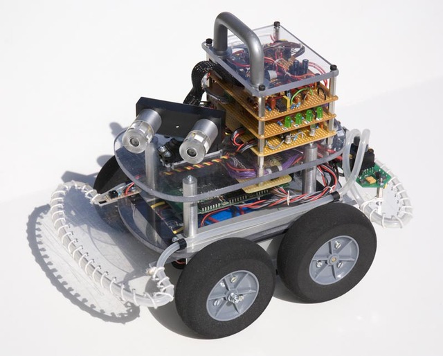
Hi, this is my first post in LMR, and I like to present my second robot. By the way I am a 17 year old student located in Sweden, in northern Europe.
The second video is the best one.
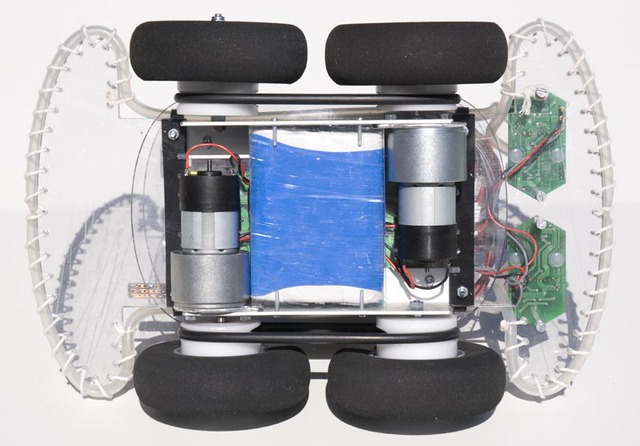
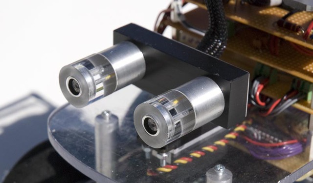
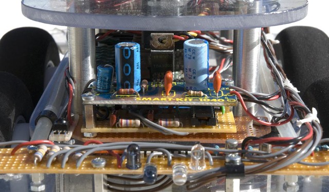
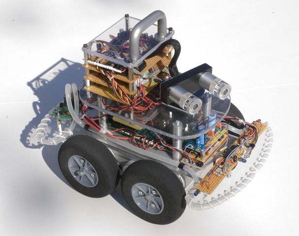
I have designed and build all the parts of the robot, including the ultrasonic rangefinder. The only exception is the H-bridges for the motor drives, and of course the pressure sensors. The H-bridges are mounted on a surplus item containing IPS-031 power switches and optocouplers. The H-bridges are controlled by two PIC16F690.
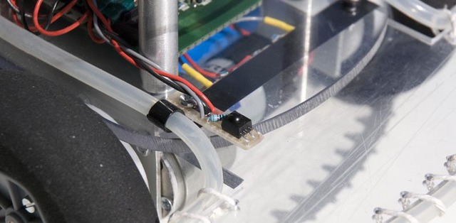
The ultrasonic range finder is also constructed around a PIC16F690. It is probably not as efficient as the ones that are available in the market. But I have learned a lot by building it myself.
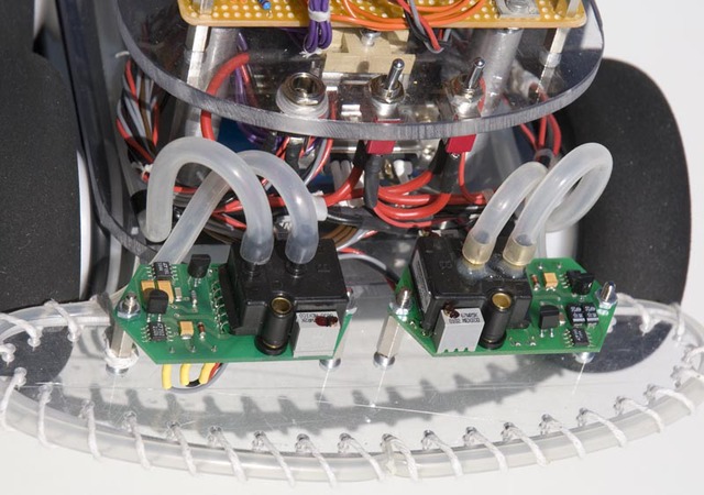
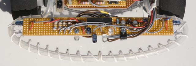
The design of the bumper sensors are also a bit odd. I use a silicon hoses which are connected to a couple of pressure sensors. The analog pressure outputs are converted to digital by two PIC12F863. These MCUs also controls the LEDs in the bumpers.
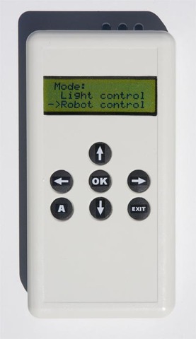
The main “brain” of the robot is a PIC16F887 running at 20MHz. This PIC also listens to an IR-receiver, which can receive “high-level commands” form a also home built remote controller. This controller can also be used for completely different purposes, like controlling the lights in my room.
Updated 16/10 2010
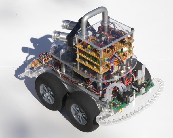
New features: I have built four infrared sensors, added a speaker controlled by a SpeakJet voice synthesizer chip and improved the firmware. Now the robot has a little bit more complex behavior and support for the new features. I have also made a new video.
The four infrared sensors are mounted on the front bumper. One facing forward, one upward, one left and one right. The upward facing sensor is just to prevent the robot from driving under my bed and other similar things. All four sensors are all controlled by a single PIC16F690 microcontroller. The MCU reads the analog signals from the IR phototransistors with and without the IR LEDs on. If the difference is greater than a specified number there is an obstacle in that direction. The PIC16F690 then sends this data to the main microcontroller as four digital signals.
The SpeakJet voice synthesizer chip is controlled directly by the main MCU. The Speaker is connected to the SpeakJet through an audio amplifier. That makes the robot able to speak really load if I want it to. The SpeakJet also makes some beeps and sound-effect when the robot sees obstacles.
Hope You like my robot, Regards Axel
Navigate around while avoiding obstacles with ultrasound, infrared light and air pressure based bumper sensors.
- Actuators / output devices: one servo, 2 geared motors, speaker
- Control method: autonomous, infra red semi-controlled
- CPU: 2x PIC12F683, PIC16F887, 4x PIC16F690
- Power source: nimh, 7.2V, 2000 mAh
- Programming language: Assembler, C#
- Sensors / input devices: IR, bumper sensors, Home built ultra sound
- Target environment: indoor