


My new Buggy-Bot
Hi,
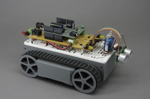
Here's my latest Buggy-bot? and my best one so far, why? well having a good quality chassis is a start, rather then bits I've thrown together in the past. The build quality is very good, the motors while quite separate run at the same speed, well very close!! so it travels in a straight line and not a curve. Now when it hits a chair leg the tracks allow it to run up it, but then the tilt switch comes in to play and it reveses for a time and does a turn! This is also the first time I've used PWM to control the speed, it starts off slow but soon gains speed to 99%+, slows down when an object is detected, reverses and looks both ways for the longest clear run and goes for it, etc,etc.
But its not perfect! it still gets trapped under the radiator, or the front corners jam somewhere (may have to fit a bumper switch??) one of the driving gears has an hole in it, so thinking to use a (or 2, one per motor) slotted opto switch/s to detect motor stall!
The PCB's are my own, the top one being my version of the Picaxe shield, but with a 20M2, with memory and RTC, with the 20M2 all port pins are in line and brought out to the 8 pin headers in neat orderly rows (unlike the Arduino, which are all over the place). The bottom PCB has the L293 motor driver chip, sound, LED indicators...... Batttery charging is in situ, 6xAA's give about 7.3V to the motors and a LDO 5V reg powers the rest.
I have more work to do yet, so work in progress.
Oh by the way! I'd love to have your comments, advice good or bad. Why not take a look at http://melsaunders.x10.bz
Regards
Mel.
: Navigate around via ultrasound, avaiding objects and crashes, most of the time!
- Actuators / output devices: servo, geared dc motors
- Control method: autonomous
- CPU: Picaxe 20m2
- Operating system: Win-7, Macintosh OSX..
- Power source: 6x AA Nimh
- Programming language: Picaxe basic
- Sensors / input devices: SRF05 Ultra Sound, Tilt switch
- Target environment: Indoor and out, will climb well over rough terrain