


My LMR Start Here - CDR ( Compact Disc Robot )
This is my first robot. I started fiddling with microchips as a break from high level programming. I like feeling more in touch with the low level operations I rely on everyday. This little guy started life as a version of Frits' start here robot. I called him KiBHuJu ( Kit Bashed Hunk of Junk ). The Microchip Pic 16F88 is programmed in Assembly on Linux, using gpasm. The programs are loaded with picp. Testing was done with gpsim. Props to all who work on this toolchain!
I couldn't wait for parts, so I bought the Ping Ultrasonic sensor from Radio Shack. I had a Parallax servo from a Basic Stamp kit I bought to get started in electronics. I was still waiting for the motors, so I soldered up a mess of a board and got the servo and sensor working. Still, waiting on Solarbotics, I added the piezo speaker.
The motors arrived, and I promptly trashed them ( see my blog for the whole grisly story ). I decided to rebuild the board, so that I could use it in many development projects. The board now looks like this:
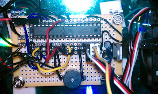
It could use a few more things yet. It has two 18 pin chip sockets, a piezo speaker, a 5V regulator, cap smoothed pins for 2 motors, and a power switch. What it needs is a reset switch and a header for bootloader programming.
Here is the schematic:
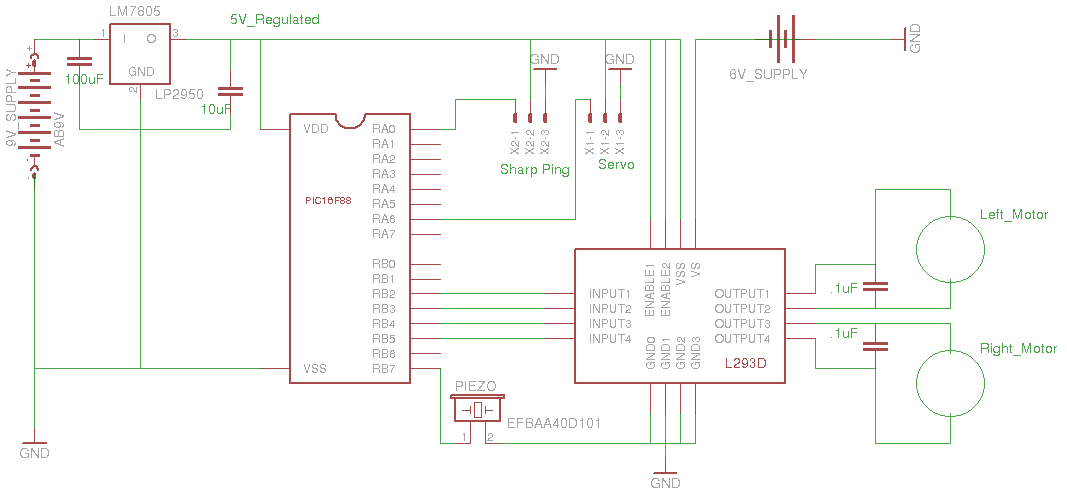
The power solution is less than optimal. I used 4 AA rechargeables for the motor supply. I decided to wire a second 9V battery in for the board supply. I am really an electrical tyro, so I took the safest approach. For me, the fun is in programming the chip in a low level language.
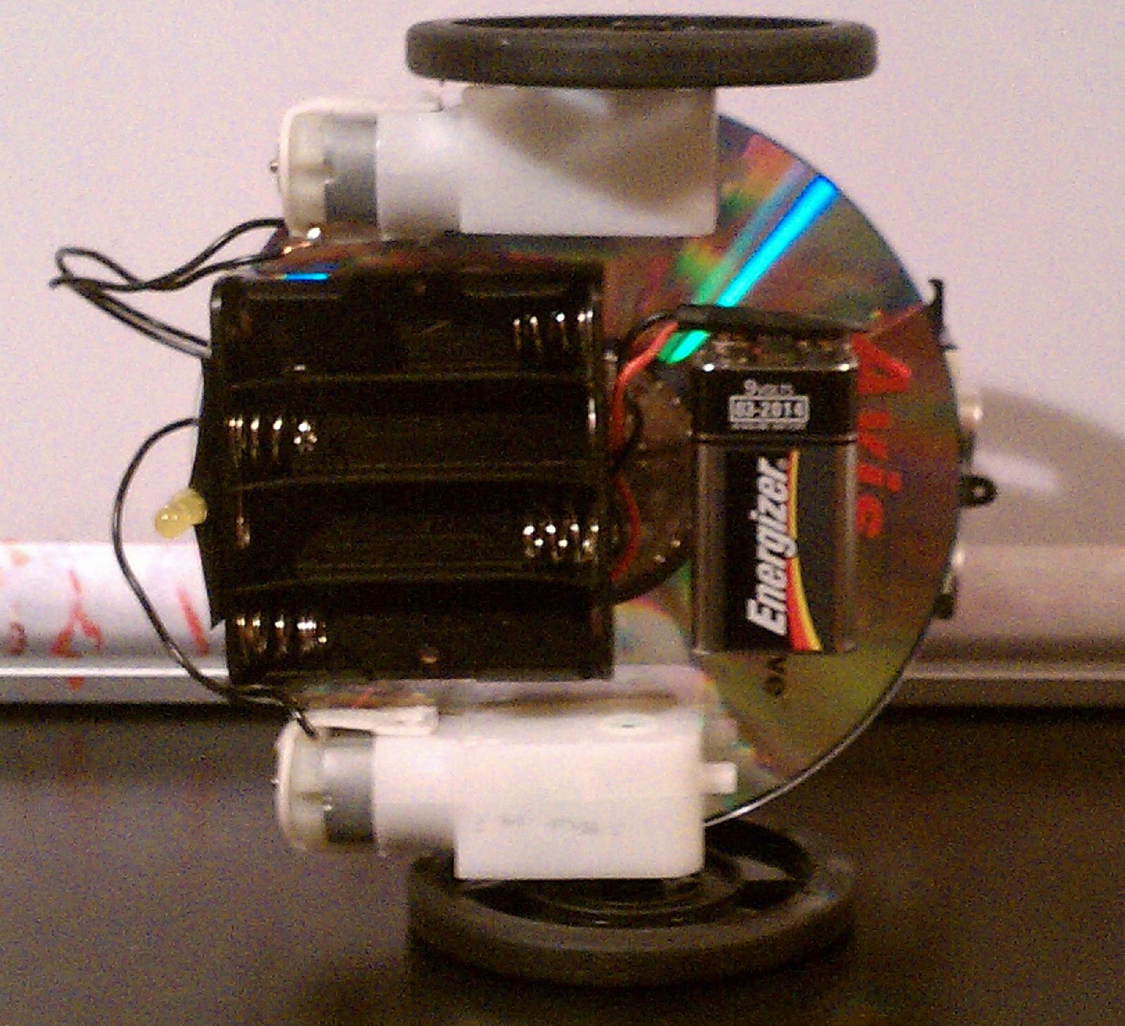
Here is the bottom of the robot. You can see the power arrangements. The wires run up through the center of the CD hole.
This was definitely a learning robot. I learned about line noise, rebuilt the gear motors, got the peripherals working, and learned that I want a bootloader.
I've started work on a bootloader. I've got the Pic code done. I'm just about there with a python programmer. I need to add a reset switch and header for bootloader programming to the board. That and some "neating" stuff like shrink tubing for the connections. I also need to build an RS232 shifter for programming.
This is a really satisfying hobby. Thanks so much for providing a space to share!
Explores via Ultrasound, plays "Zelda's Lullaby" when stuck
- Actuators / output devices: 2 GM9 motors, 1 Parallax Standard Servo
- CPU: Microchip Pic 16F88
- Operating system: Open SuSE 11.2 Linux
- Power source: 6V rechargeable for motors, 9V battery for board
- Programming language: Assembler
- Sensors / input devices: Ping ultrasonic
- Target environment: indoor on smooth surfaces