


My first robot using R/C car base
Hi guys! I want to submit to you my first project (and I hope not last). I know this good site for a long time and now I decided to share my robot.
I’m sorry for my bad English (if there are any grammar mistakes) :)
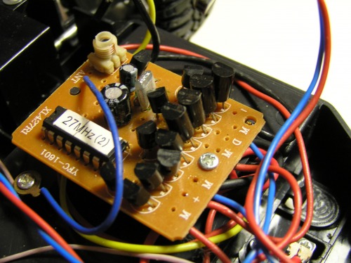
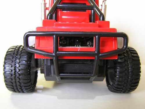
I chose R/C car for a robot base. I wanted to save original R/C control and to make autonomous control. Operating regime is selected by a switch that is located near accumulator in the bottom of the car. I connected wires from DC motors parallel to the original and to my developed circuit. I noticed that original transistors in H-bridges got very hot even after short using; therefore I decided to use more powerful transistors. Firstly, I made 2 H-bridges with transistors КТ972 (analogs are BD677, BD679, BD681). But it has turned out, that they were not better: they also got very hot and had a large voltage losses (my robot moved very-very slowly, sometimes only with my help).
Therefore I replaced 8 transistors by one dual full-bridge driver L298N with small aluminum radiator.
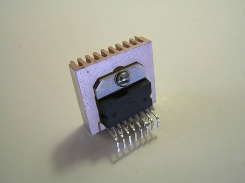
My car moved obviously better, but not so fast, using original circuit and not for a long time (because of huge heating and, therefore, of the low efficiency).
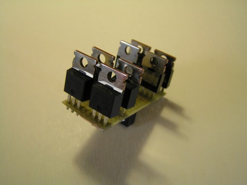
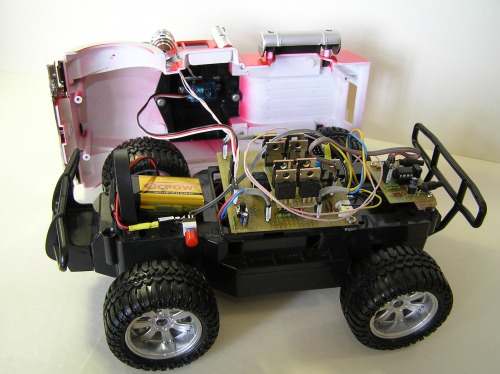
Finally I made dual H-bridge module using MOSFET IRFZ46N. I had to supply such circuit with operating voltage VGS about 10 V that MOSFET become saturated and that minimize the energy-losses. Because power supply of the microcontroller is only 5 V, we can’t connect MC pins directly to the bridge, but we have 9 V from 6F22 battery. Obviously we should use transistor switches (e.g. I used NPN transistors SS9014). I’m satisfied with this module, because now my car can move very fast and therewith transistors in the H-bridge stay comparatively cold.
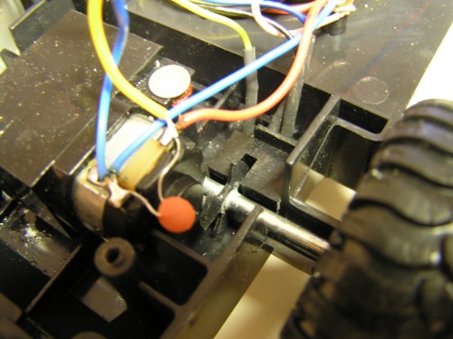
For counting of the distance I installed homemade incremental encoder, that consist of an optocoupler and simple interrupter disk (it was made from a little piece of a plastic folder and can give only 3 counts per revolution), that was mounted on the back axle.
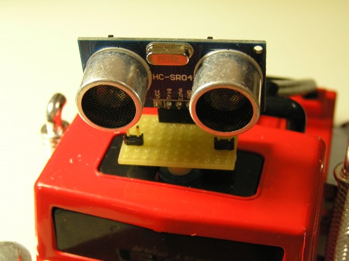
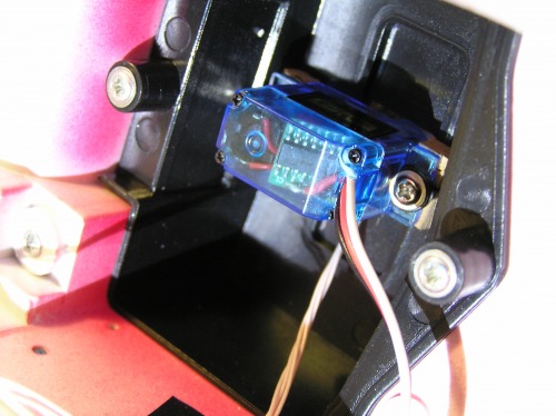
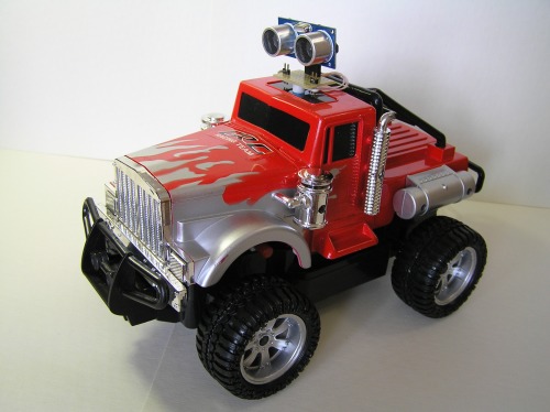
As the main obstacle detection sensor I used ultrasonic ranging module HC-SR04, that was mounted on the top of the car and it is moved constantly by the micro servo.
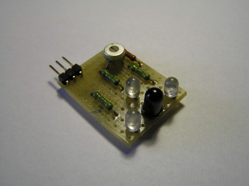
In the back part of the car was installed homemade IR obstacle detection sensor. The making and tuning of this sensor was a real headache for me :) Firstly I used 3 IR LEDs and an analog IR sensor. But it was very sensitive to a sunlight and therefore unusable. Than I made next version of the sensor using digital receiver TSOP1736, pair of the IR LEDs and a microprocessor ATtiny13, that modulates IR light and forms necessary output signal. Digital receiver is very sensitive therefore I had to limit the IR LEDs intensity. Though now this sensor works perfectly.
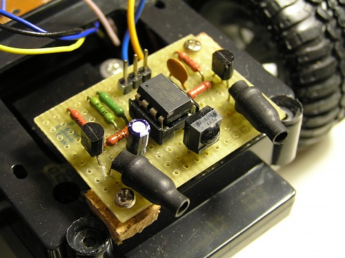
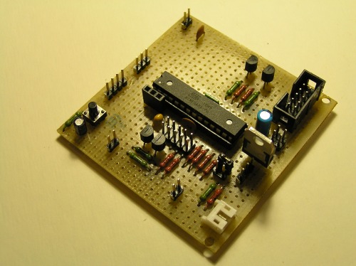
Finally I made a main board. For power supply of the microcontroller and the sensors the voltage regulator LD50V was used, that converts 9V from the 6F22 battery to stable 5V. In addition, I advise you to use the ceramic capacitors (100 nF), that are soldered closely to the power supply PINs of the microcontroller and that filter high-frequency interference.
Thank you for your attention!
Navigate around via ultrasound
- Actuators / output devices: 2 dc motors, micro servo
- Control method: autonomous
- CPU: atMega8, ATtiny13
- Power source: 9 V (6F22), 4.8 V (Ni-Cd accumulator)
- Programming language: Assembler
- Sensors / input devices: ultrasonic sensor, IR obstacle detection sensor, incremental rotary encoder
- Target environment: indoor