


My first robot "Picle"
Hi,
This is my first attempt at building a robot that will avoid obstacles. To begin with Picle has already had one major revision including a chassis change, unfortunatley i do not have any photos of it as it started life but i have kept all the parts that were used and will post some photos and an explanation of each followed by a descripion of what that compoent was replaced with and why.
After this is out of the way you should have a good understanding of how my little guy is built and i will then give a brief explanation of the software it is currently running and post some photos of how it currently looks, followed by some talk about Picle's limtations and how i plan to overcome these which i guess you could think of as my planned changes for Picle.
Chassis
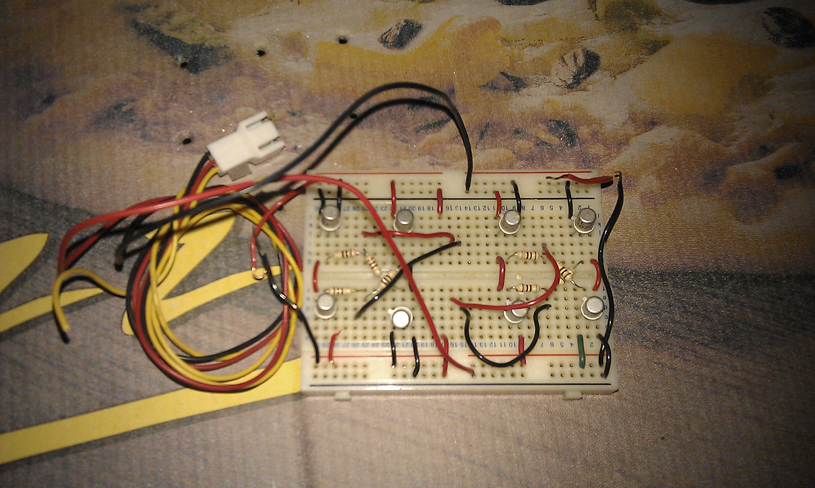
Picle's original chassis was made out of a single piece of copper clad board that was scored and bent 90 degrees before being soldered along the seam for rigidity. The electronics were all housed on a small breadboard and the mtors and sensor was glued to the copper clad board.
This configuration weighed a lot for its size and proved to be unstable. It also proved not to have enough space to expand the electronics. I must say however that it did work and i was very pleased with myself for having built my very first robot. After my initial excitement had passed i decided to revisit the chassis design and came up with the idea of useing stripboard as the chassis instead of the copper clad board, this saved a lot of weight had conveniently gave me a lot of convenient space to mount the circuitry. I added a second piece of copper clad board to the top of the motors to add a bit more strength and further expand the space for electronics (See planned changes for more information on why).
Motors
The motors are probably the only thing that hasn't changed on Picle. I am useing a pair of modified Futaba S3003 servos as drive motors. The servos were not only modified for continuous rotation by removing the mechanical limit and the potentiometer from inside but whilst i was at it i removed the circuitry aswel and soldered wires directly to the motors, essentially turning them into small geared motors instead of servos.
Motor control
In the begnning i used a discrete H bridge setup to control Picle's motors, this was mainly because i didnt have a H bridge ic in my parts box but i did have a load of BC107 transistors, it really is a lot neater to use a IC instead of discrete circuitry. That being said i have not noticed any difference in opperation between the two and the only advantage i can see is the space savings provided by the IC.
This Discrete H Bridge was replaced with a SN754410NE IC. This saves both space and a small amount of weight and it is far easier to troubleshoot should somethig go wrong.
Wheels
The wheels i used originally were constructed from cd's glued to servo horns, These wheels found it hard to get good traction on most surfaces but did just about work.
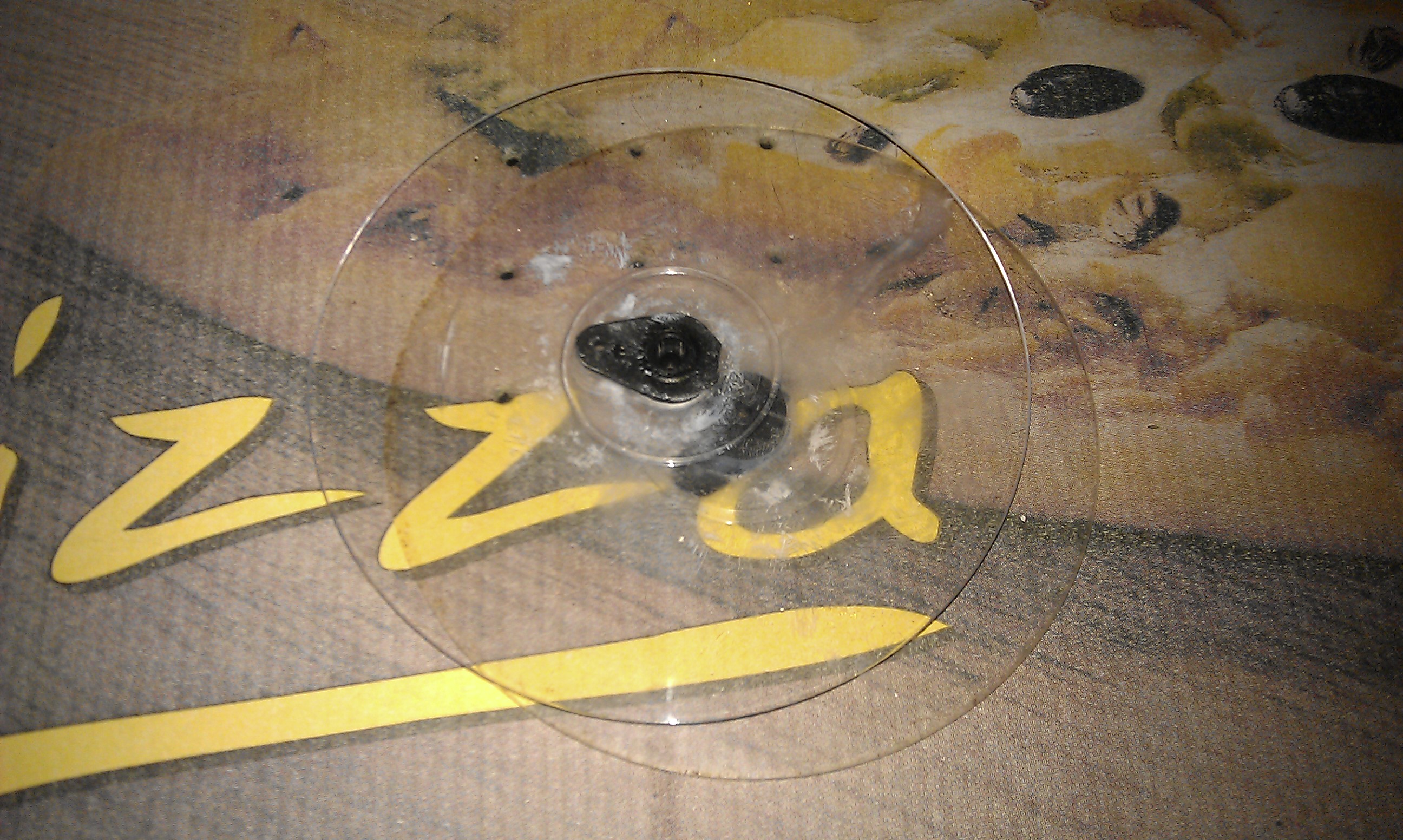
When i ordered the SN754410NE and the stripboard for the chassis i also found the same website was selling wheels designed to mount to servos failry cheaply so i added a couple of them to the order. These work much better, they are smaller in diameter so Picle can move about a bit faster and there is less strain on the motors, they also have very grippy rubber tires that dont seem to struggle on any surface i have attempted to use them on, all in all they were a very good buy.
Sensors
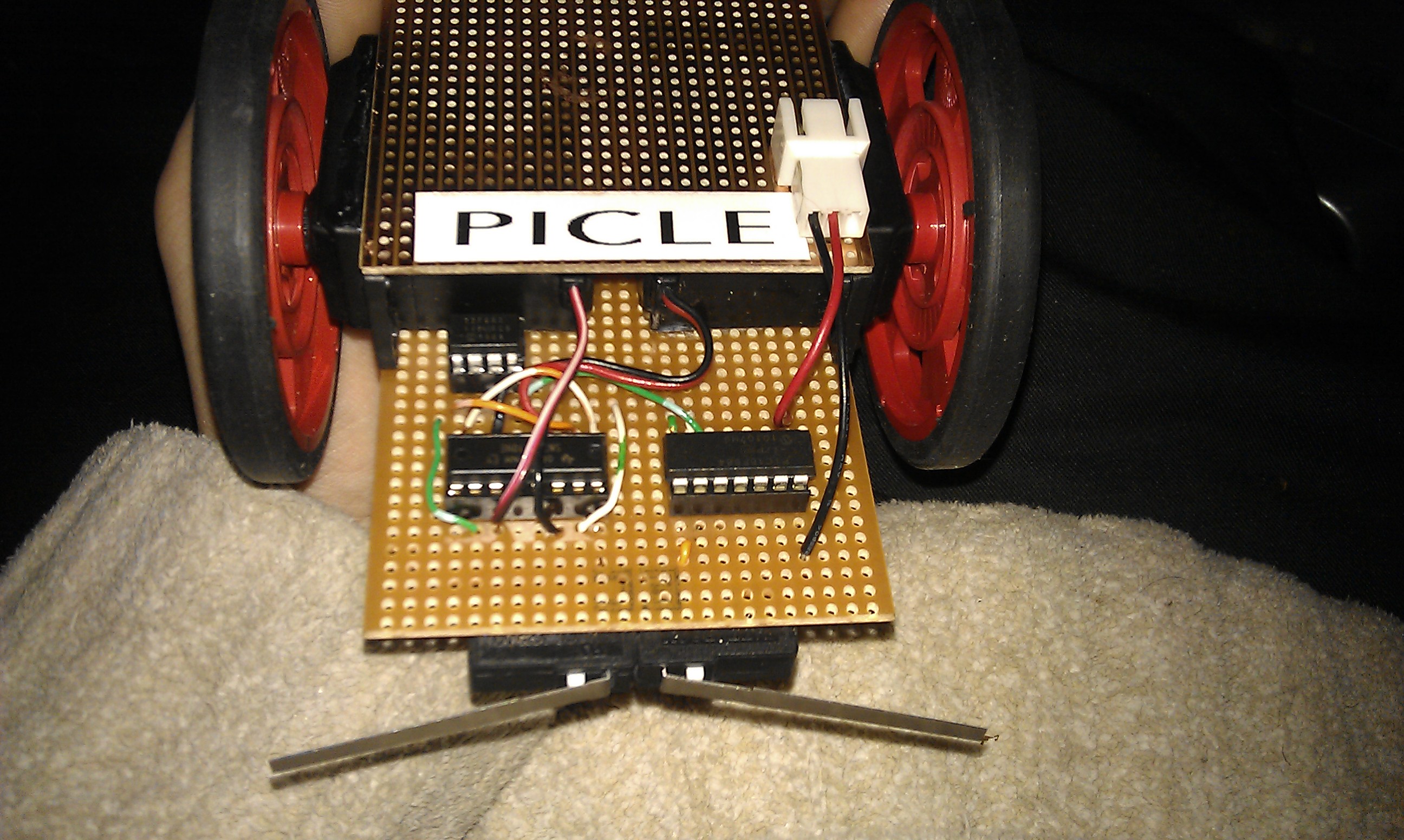
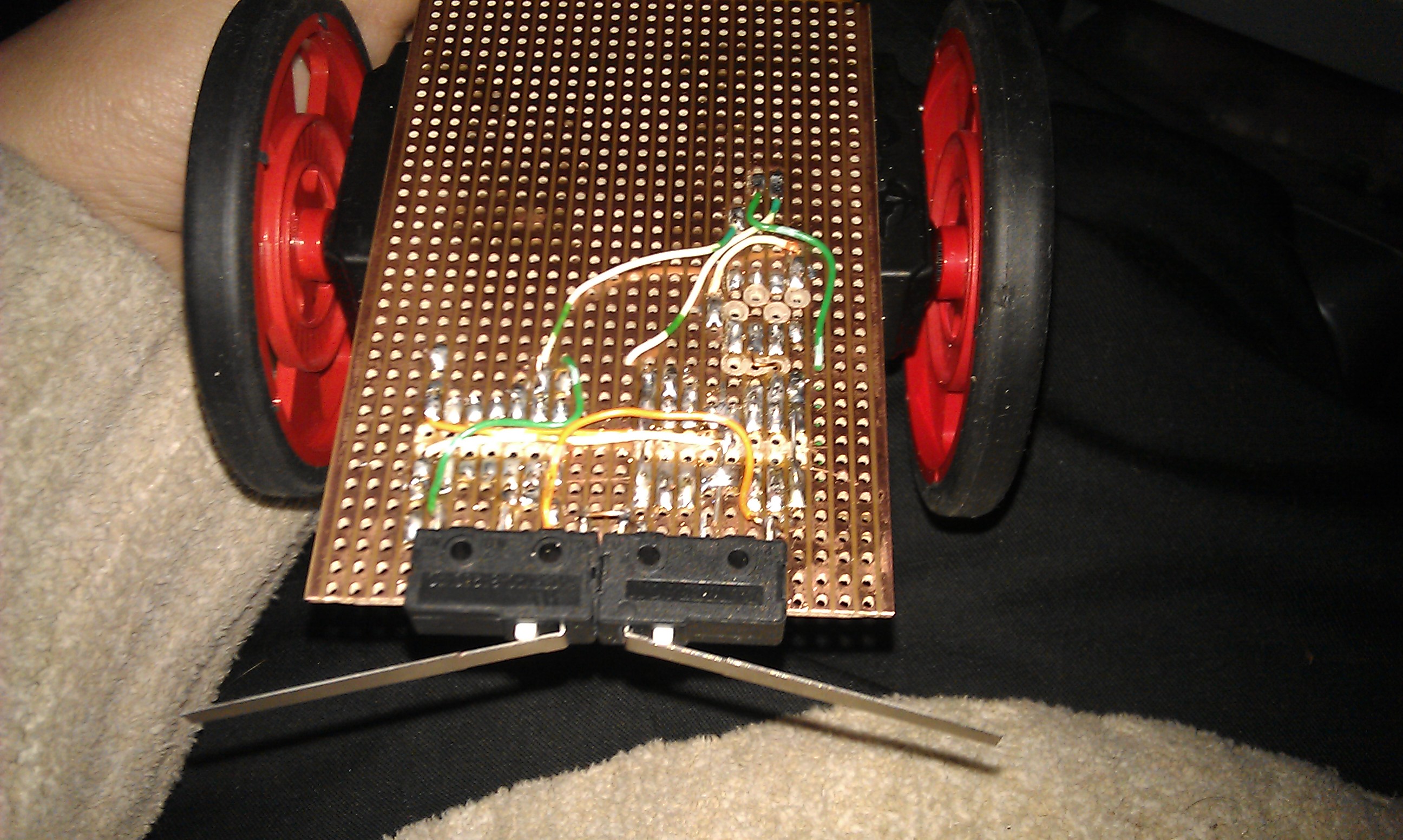
As can be seen in the picture of the old chassis above, Picle used to use a single switch in the center of the chassis to provide collision detection. This was far from ideal and more often than not obstacles would simply miss the switch entirley. I replaced this single switch with a pair of switches that i bought at the same time as the rest of the stuff i ordered so far for this project.
Picle's Brain
Picle, as his name suggests, uses a pic microcontroler as a brain. Initially tis was a small PIC12F675 that was located between the two H Bridges on the breadboard but I changed this for a PIC16F684 when i moved to stripboard to allow for future expansion. The Program running on the 16F684 is the same one that wasoriginally running on the 12F675, I wrote 2 sensor compatibility into it right from the start.
Software
The software that is running on the Pic is currently very basica apart from a few timing tweaks has not changed much. It was written useing a program called flowcode which lets you lay out what you want the pic to do in the form of a flow chart and it then automatically creates the C code and HEX from that flow chart. This piece of software is extremley easy to use for beginners.
Basically the software runs in a loop, It checks the left sensor and if there is an obstacle in the way it moves backwards and to the left. If there is no obstacle it caries on to check the right sensor, if it detects an obstacle it moves backwards and to the left (noice it always turns the same way, macros and laziness on my part) If no obstacle is detected it ses the motors moveing forwards. and then it repeats the whole process over and over again untill i disconect the battery.
It is actually slightly more complicated than this and from tweakng includes a debounce macro for the switches to help avoid "false collisions" and a delay macro that is called a total of 3 times during the "backwads and to the left" part of the code.
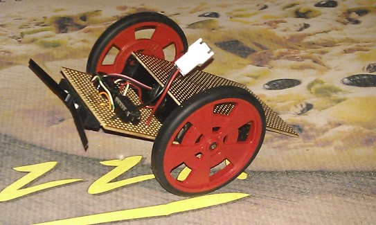
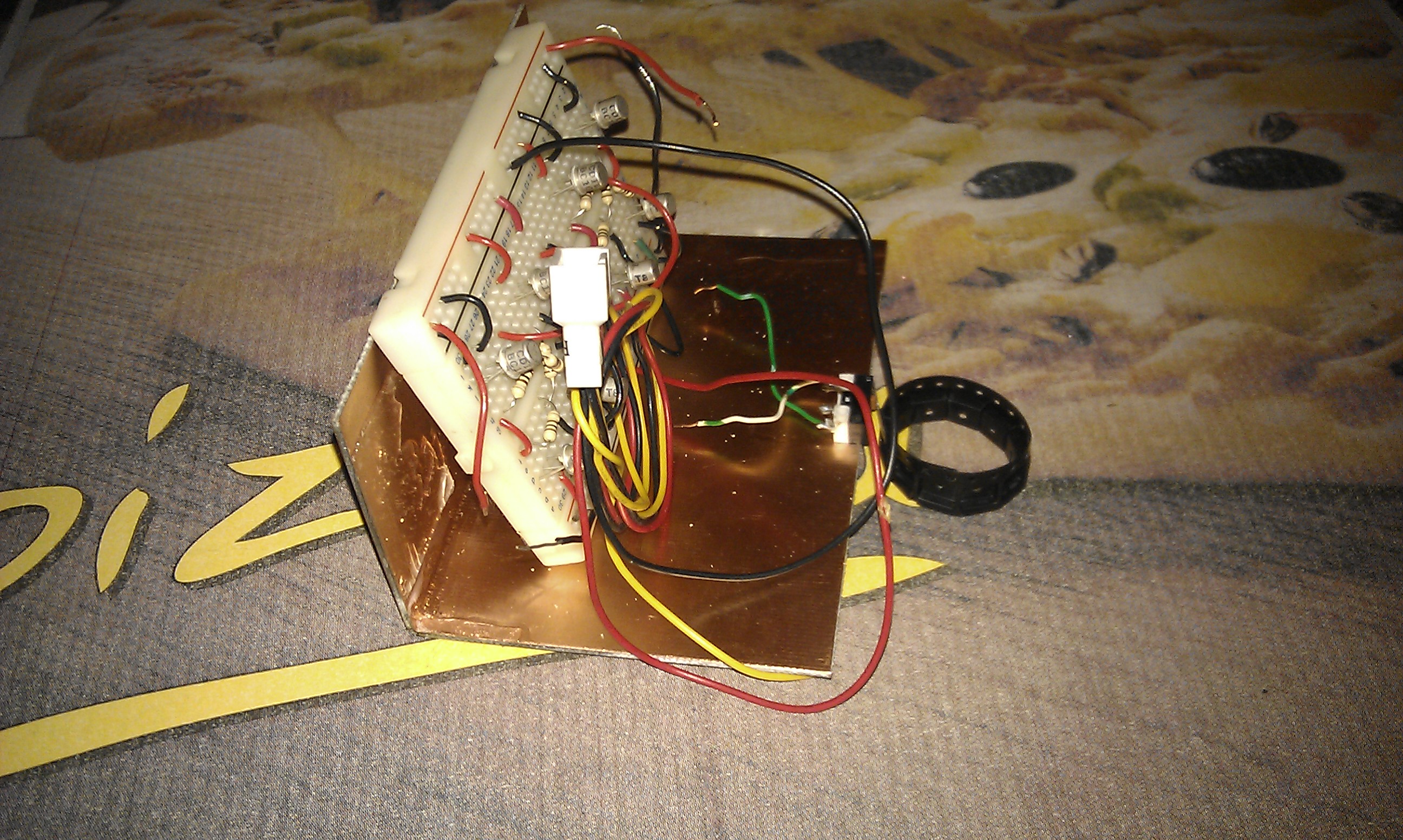
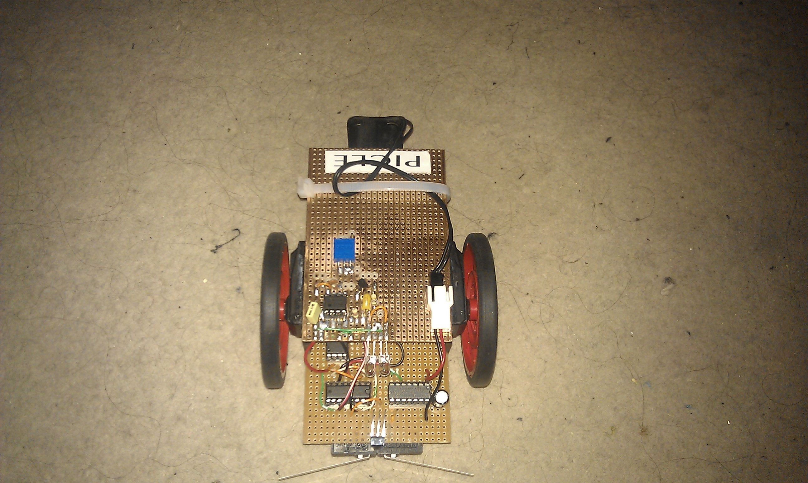
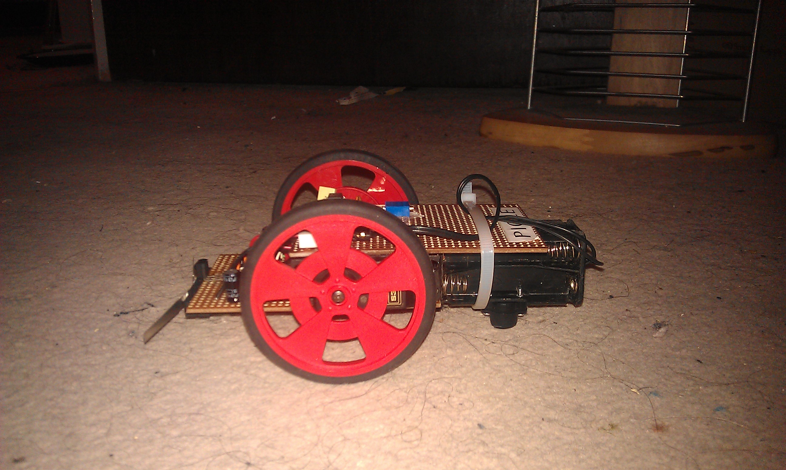
Current Picle Photos
If you are anything like me then you probably skipped the rest of the page looking for this section, If thats the case then please read the rest, i would love suggestions on how to improve the design further.
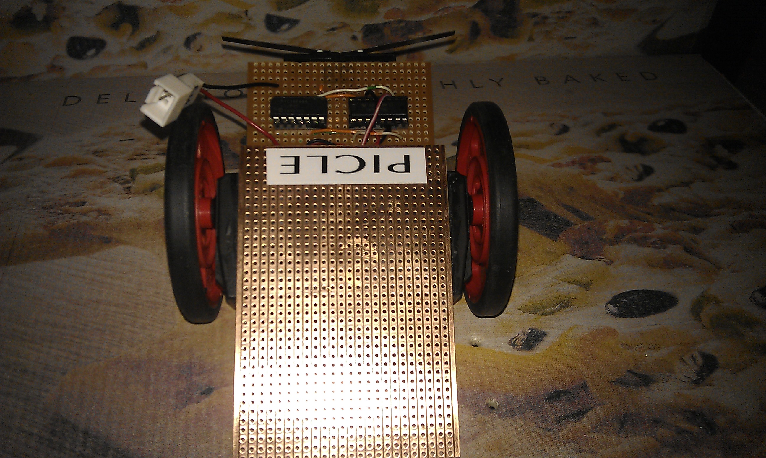
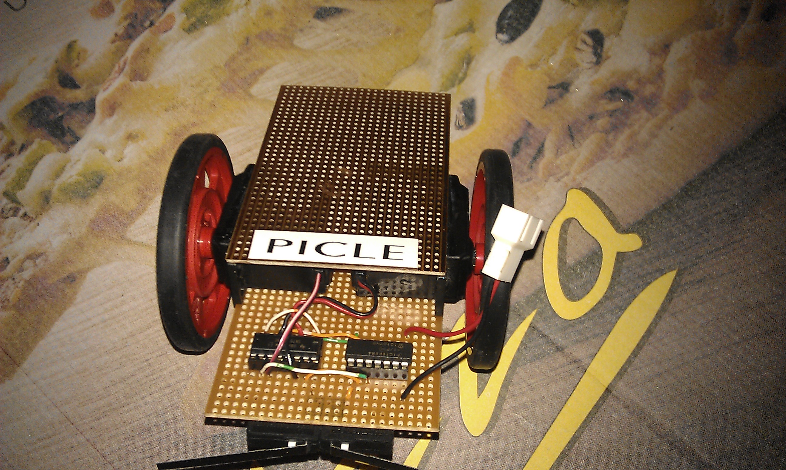
23/12/11:
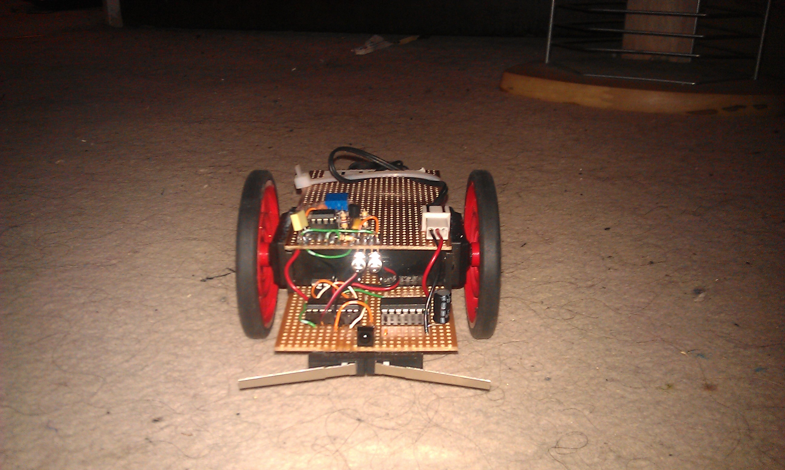
24/12/11
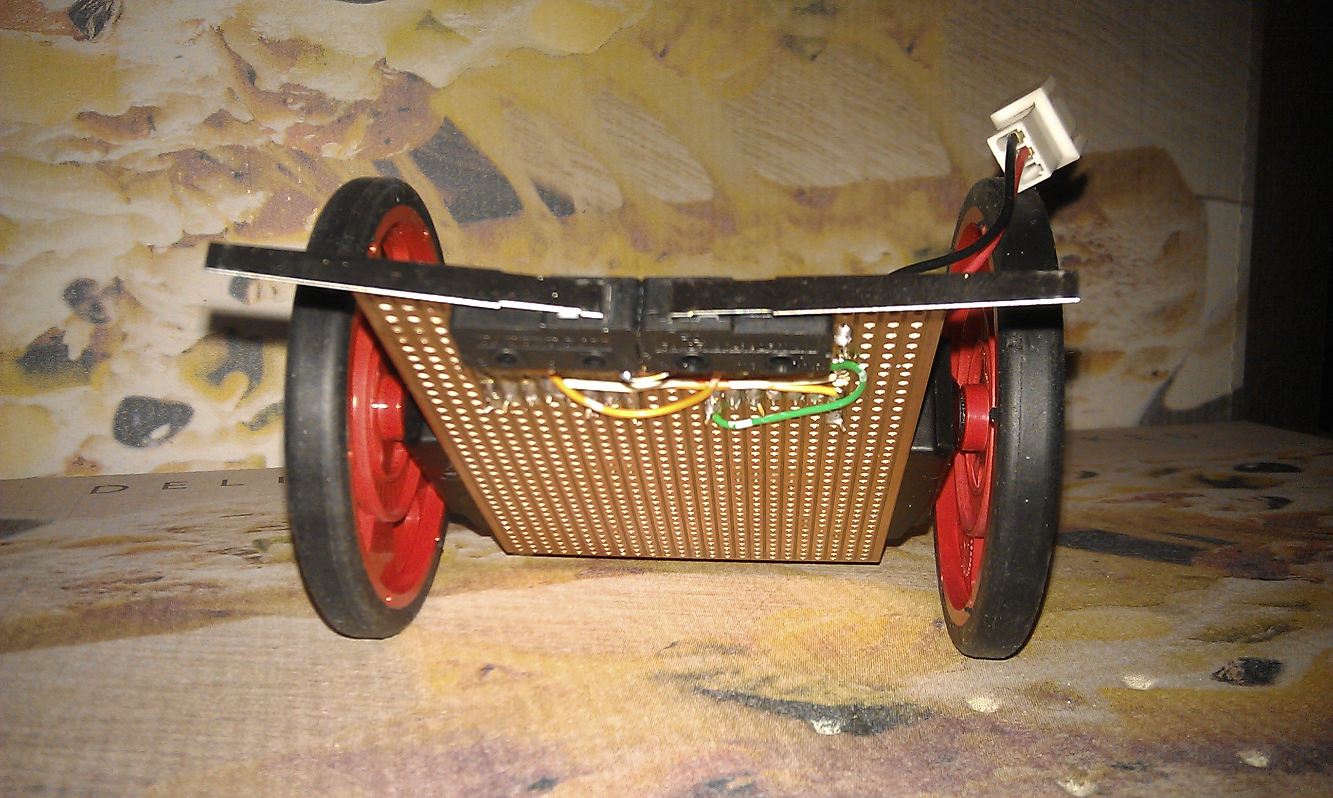
31/12/11
Planed changes
I have a few changes planned for picle already and i will list them and the reasons for them here in the order i plan to do them in.
1) (Completed) Currently the H Bridge is running directly from the main Pic. This configureation uses up 4 I/O lines and 27% of the availible ram, I have left space on the board behind the H Bridge ic so that i can fit a PIC12F675 in there that will be responsible for controling the motors. This Pic will run the originall code (shouldnt even have to modify it) and will allow 2 I/Olines from the main processor to control the H-Bridge, at the same time freeing up ram in the main processor for other tasks. Currently it is set up the way it is because the code i am working on is in fact the motor control code that will eventually reside on the 12F675.
23/12/11:
So far the socket for the 12F675 has been added, power and ground are going to the correct pins, PIC12F675 has been programmed and fitter to the socket. I decided to modify the code when i was at it because debounce wasnt really needed here so i got rid of it and now the code allows for going forwards and turning left or right in reverse depending on the state of the two input pins. Hopefully i will have motor control passed over to this chip and have it tested tonight, otherwise it will probably have to wait untill monday night or tuesday morning.
24/12/11:
Managed to get it finished, it was vey glitchy at first and i found a couple of very small solder bridges and tried a PIC12F683 in place of te 12F675. It is less glitchy now yet occasionally it still glitches, i took all the debouncing routines out but now i remember it was glitcing slightly before i added them in originally so i think i will add them back in on the 16F684 and swap the 12F683 (complete overkill) back to the 12F675 so i can save the 12F683 for another project that requires more code space / ram.
I figured over christmas dinner, maybe the motors are causing interferance. I managd to get a little tinkering time in when we got home so i added a smoothing capacitor to the power rails and all glitches have dissapeared when useing the 12F683, the 12F675 is still not working correctly but the two chips cost the same so Picle can have a small upgrade and gets to keep the 12F683 for motor control.
2) (In Progress) I noticed whilst testing the new motor control setup that if picle encounters a corner that it gets stuck in a loop revrsing and turning into the opposite wall over and over again. I need to write some way for Picle to know if this is happening into the code so that it can take evasive measures in the form of either a 180 degree turn or turning the opposite direction to normall. If anyone has any other suggestions on how to overcome this then please say.
26/12/11:
I played around with the code a bit, My solution is far from ideal but it does work. I have added some code to the motor control PIC that basically adds 1 to a variable everytime the left turn routine is triggered and then if the left turn has been triggered 5 times it triggers it clears the variable and trigers a second left turn (bringing it to 180 degrees). This will stop picle from getting stuck in corners but also means that during normal operation evvery fifth time Picle encounters an obstacle with its left sensor it will just turn around 180 degrees, not a big problem but i am sure there is a better way to stock Picle getting stuck in corners and as such i am not going to mark this as completed, If anyone can come up with any suggestions i would be gratefull.
3) (Completed) At the moment picle drags itself around on the edge of the pcb, this seems to work fine but the collision sensors are quite high up and at an odd angle. I have ordered one of those little ball point third wheels to fit to the far edge of pickles lower circuit board in order to ballance it out a bit better and bring the switches down to a more sensible level.
28/12/11:
The parts arrived today and i have had a change of plan, i have mounted the third wheel to the battery holder instead of the pcb. The battery holder is normally held onto the top of the pcb with a couple of elastic bands but i think it works better lower down and so mounted the wheel to it and now it is held onto the bottom of the top pcb with elastic bands, I also realised that i have not posted any pics of Picle with the battery holder atached, Obviously i will have to update them soon.
4) (In Progress) Although the sensor setup Picle is using now is much better than the oriinal single switch setup there is now a "dead spot" right in the center between the two switches. It isnt much of a problem but on od ocasions Picle has got stuck against chair legs or corners of objects.I Plan to overcome this with the use of an IR sensor / LED combination, I have ordered the parts to construct this (along with the third wheel thingy) and am awaiting delivery. The current plan is to drive the IR LED from a 555 based oscilator and not from the PIC's PWM output. We will see how this works out and i might possibly change this in the future. I am mainly useing IR for this sensor because i want to experiment with different types of sensors, one of the main purposes of Picle is for me to get to grips with using different kinds of sensors so i have a better understanding of how they work for future projects.
28/12/11:
I have started to solder up the 555 circuit that will control the IR led's and i have mounted the LED's and the sensor. I do plan to shield the sensor a bit so that it isnt triggered by stray IR from the led's. Hopefully i will get the soldering finished tonight or tomorrow and i will update the pics when i am done. All that is left after that is to modify the code so that it takes into account the new sensor. Picle is starting to look more and more complex, there are now 4 ic's in total and a whole load of other components. Fingers crossed it still works after this latest surgery!
31/12/11:
Not really much of an update, I have been busy upgradeing the PC that i use for programming the pics From a P4 to a Core2Duo, It now runs windows 8 Developer Preview and i am happy i can announce that Elnec programmers and Flowcode both run flawlessly under Windows 8 64Bit.
Back to Picle though. I have done a little bit more soldering on the 555 Circuit. All that is left now is to solder a 15K resistor in but alas i cannot find anything close in my parts box so i am going to have to search a bit deeper through the stuff i have not unpacked yet from the last house move. In the mean time i have added a couple of new pics for you to see my progress.