


My first Robot controlled by a chipKIT Max32 using a Microchip PIC32 microcontroller
My Robot is based on the DFRobot 4WD Arduino-Compatible and it is controlled by the chipKIT Max32.
Max32
The chipKIT™ Max32™ is based on the popular Arduino™ open source hardware prototyping platform but adds the performance of the Microchip PIC32 microcontroller. The Max32 is the same form factor as the Arduino™ Uno board and is compatible with many Arduino™ shields. It features a USB serial port interface for connection to the IDE and can be powered via USB or an external power supply.
The Max32 board takes advantage of the powerful PIC32MX795F512 microcontroller. This microcontroller features a 32-bit MIPS processor core running at 80 MHz, 512K of flash program memory and 128K of SRAM data memory. In addition, the processor provides a USB 2 OTG controller, 10/100 Ethernet MAC and dual CAN controllers that can be accessed via add-on I/O shields.
The Max32 can be programmed using an environment based on the original Arduino™ IDE modified to support PIC32. In addition, the Uno32 is fully compatible with the advanced Microchip MPLAB® IDE and the PICKit3 in-system programmer/debugger.
Note that initially I have used the chipKIT™ Uno32™ but I have reached the limit of the flash program memory (128K) when I have added the TCP and WIFI libs, so I have migrated to the chipKIT™ Max32™ that allows 512K of flash program memory.
Four-wheel-drive
I use the Baron four-wheel-drive robot from DFRobot with 2 encoder sensors in order to retrieve the speed of the two front motors right and left. This is useful to control the direction and to implement a PID processus. The assembly of the encoders is described in the doc installation-method-fit0029.pdf. You can also get the complete installation doc here
Warning, there is a design flaw in the mounting encoders because they rub.
Therefore, it is necessary to add a nut on the screw that secures the encoder so that the disc does not rub it in his rotation.
The specs are:
- Complete Machine Weight: 614g
- Wheel Diameter : 65mm
- Highest Speed: 61cm/s
Engine Feature:
- Gear Ratio : 1:120
- No-load speed (3V): 100RPM
- No-load speed (6V): 200RPM
- No-load current (3V): 60mA
- No-load current (6V): 71mA
- Stall current (3V): 260mA
- Stall current (6V): 470mA
- Torgue (3V): 1.2Kgcm
- Torque (6V): 1.92Kgcm
- Weight : 45g
Power
I use a block of 5 AA batteries 1.5 V for a total of 7.5 V to power the chipKIT Max32 via the external power connector.
The chipKIT Max32 provides an regulated output voltage of 3V and 5V used to supply the other components: servos, IR sensor, compass ... with the exception of the engines that are powered by one battery Lipo 2S 7.4V 350mAh
Motor interferences
The engines used are not brushless, that is to say they are made of brush that transmit power to the rotor (rotating part of the motor) and rub on an armature. This friction produces sparks that cause parasitic currents.
To remove these currents, I added a 100 nF capacitor non-polarized (ceramic) between the two motor terminals to intercept these parasitic currents. You can also add two other smaller capacitors (10 nF) between each terminal and the metal casing.
In all cases, the capacitors should be soldered close to the terminals for reasons of efficiency.
H-Bridge
A microcontroller is unable to provide the necessary current to a motor, why is it always a power stage before engines.
The speed of an electric motor is not proportional to the voltage at its terminals. The motor requires a minimum voltage large enough to start. If it is too low, the electromagnetic forces are not sufficient to combat friction. This makes it difficult to adjust the speed accurately.
The solution to this problem is clever. Simply provide the motor with a voltage that is always the same is the maximum voltage! But this voltage will be applied only in very short periods of time. By adjusting the length of these periods of time, you get to move faster or slower engines. More, we note that the motor speed is proportional to the length of periods of time. Controlling the length of time spent at the maximum voltage with respect to time without voltage application (zero voltage) is the heart of the solution. In fact, this solution is very well known in control systems and electronics and is known as PWM (Pulse Width Modulation).
A PWM signal is not generated by an H-bridge. But the fact that H-bridge is made up of transistors makes it particularly suitable to be controlled by a PWM signal. We must see the couple PWM and H-bridge as a particularly effective tool to control electric motors.
There are several models of H-bridges, I have chosen the L298 because it allows up to 4A and also because DF Robot proposes a module ready using this circuit, named 2A Dual Motor Controller. I have first used the L293D which is also a good choice but limited to 1A. As I had many problems with my soldiers, I preferred an already installed system.
One L298 is used to control 2 motors, so I use 2 L298 to control the robot. They are powered by one battery Lipo 2S 7.4V 350mAh for both parts logic and driven of the voltage.
The way to control the motor is the following:
- Enable bit allows the engine power. As previously explained it received a PWM signal.
- The pins IN1 and IN2 of the L298 are used to manage the direction of the motor. The 2A Dual Motor Controller includes several NAND gates in order to combine IN1 and IN2. So at the end, only one pin is needed to control the direction.
The connectivity between the two 2A Dual Motor Controller and the ChipKit is the following.
Pins IN are connected to the standard digital pins of ChipKIT while Enable pins are connected to the PWM pins of ChipKIT in order to use the functions analogWrite () that rely on timers Oci:
#define InMotorRight1Pin 30 // In pin of Motor controller #1 for motor right #1 connected to digital pin J9-08(PMD7/RE7)#define EnableMotorRight1Pin 3 // Enable pin of Motor controller #1 for motor right #1 connected to PWM pin J14-07(SDO1/OC1/INT0/RD0) Use TIMER_OC1#define InMotorRight2Pin 31 // In pin of Motor controller #1 for motor right #2 connected to digital pin J9-07(PMD6/RE6)#define EnableMotorRight2Pin 5 // Enable pin of Motor controller #1 for motor right #2 connected to PWM pin J14-11(OC2/RD1) Use TIMER_OC2#define InMotorLeft1Pin 32 // In pin of Motor controller #2 for motor left #1 connected to digital pin J9-06(PMD5/RE5)#define EnableMotorLeft1Pin 6 // Enable pin of Motor controller #2 for motor left #1 connected to PWM pin J14-13(OC3/RD2) Use TIMER_OC3#define InMotorLeft2Pin 33 // In pin of Motor controller #2 for motor left #2 connected to digital pin J9-05(PMD4/RE4)#define EnableMotorLeft2Pin 9 // Enable pin of Motor controller #2 for motor left #2 connected to PWM pin J3-03(OC4/RD3) Use TIMER_OC4
Encoders
2 encoder sensors mounted on both left and right front engine can calculate the motor speed.
They are connected to the interrupt pins INT3 and INT4 of ChipKIT in order to get at any time the number of ticks achieved by each engine. One encoder generates 20 voltage changes per round that trigger consequently 20 interruptions per round. I use the pins INT3 and INT4 to catch the interruptions in order to don’t busy the cpu. Be careful to define the pins as input before calling the attachInterrupt function that configures the interruptions.
The connectivity between the 2 encoders and the ChipKit is the following:
#define EncoderTickRightINT 4 // INT used by the encoder for motor right connected to interrupt pin INT4 J4-02(AETXEN/SDA1/INT4/RA15) Use INT4#define EncoderTickLeftINT 3 // INT used by the encoder for motor left connected to interrupt pin INT3 J4-01(AETXCLK/SCL1/INT3/RA14) Use INT3
IR Sensor
IR Sensor GP2Y0A21YK can detect barriers. It is connected to one of the analogic pins of ChipKIT in order to use the function analogRead () that converts a voltage to a value between 0 and 255 using the ADC module of the PIC.
This number is converted to cm follows based on the chart provided to a voltage of 3V in the GP2Y0A21YK datasheet. Note that you can also use 5V but you lose precision.
It is connected to a standard analogic pin of ChipKIT.
The connectivity between the IR Sensor and the ChipKit is the following:
#define GP2Y0A21YK_Pin 54 // IR sensor GP2Y0A21YK analogic pin J5-01 A0 (PGED1/AN0/CN2/RB0) Use ADC module channel 2/* Analogic interface is provided on pin V0 *//* Power +3V is set on pin VCC *//* Ground is set on pin GND */
IR Servo
The infrared sensor GP2Y0A21YK is mounted on a Servo in order to identify barriers in different directions, especially front, right and left.
The servo is controlled by pulses of 20 ms period and a width between 1 and 2 ms. These pulses are managed by the software PWM lib which allows to manage multiple servos with only one timer of the PIC and to connect to a standard digital pin.
The connectivity between the IR Servo and the ChipKit is the following:
#define IRSERVO_Pin 36 // IR Servo pin connected to digital pin J9-02 (PMD1/RE1)/* Power +5V *//* Ground */
Compass
A compass CMPS03 is connected to provide the direction.
This compass communicates with the PIC via the I2C interface using standard wire library. We can know the direction by asking via the I2C protocol the values of the register of the Compass.
The I2C address is defined as follow:
#define CMPS03_ADDRESS 0x60 //1100000: compass address 0XC0 on 7 bits for I2c protocolAfter several tests, I placed the compass away from the metal base of the robot motors and servos because it provided results completely wrong. Also pay attention to put it horizontally for better accuracy.
The ChipKIT Max32 handles 5 max I2c interfaces but the standard wire library manages only 1. By default, this lib uses the I2C1 but I can’t use this interface because the corresponding pins are shared with INT3 and INT4 that are required by the encoders. So I have updated the core file Board_Defs.h in order to use I2C2 interface instead of I2C1.
#define _TWI_BASE _I2C2_BASE_ADDRESS
#define _TWI_BUS_IRQ _I2C2_BUS_IRQ
#define _TWI_SLV_IRQ _I2C2_SLAVE_IRQ
#define _TWI_MST_IRQ _I2C2_MASTER_IRQ
#define _TWI_VECTOR _I2C_2_VECTOR
#define _TWI_IPL_ISR _I2C2_IPL_ISR
#define _TWI_IPL _I2C2_IPL_IPC
#define _TWI_SPL _I2C2_SPL_IPC
Moreover, I have connected these pins to +5 V via a pull-up resistor of 1K.
The connectivity between the Compass and the ChipKit is the following:
/* Compass *//* I2C interface is provided on pins: *//* 1 = Power +5V *//* 2 = SCL connected to J3-09 (SCL2/RA2) *//* 3 = SDA connected to J3-11 (SDA2/RA3) *//* 9 = Ground */
Temperature
A temperature sensor TMP102 is connected to provide the temperature.
This temperature sensor communicates with the PIC via the I2C interface using standard wire library. We can know the temperature by asking via the I2C protocol the values of the register of the sensor.
The I2C address is defined as follow:
#define TMP102_ADDRESS 0x48 //1001000: temperature sensor address 0X90 on 7 bits for I2c protocolRefer to the previous Compass section for the details regarding the I2C connection.
Camera
A camera is connected to make pictures.
This camera communicates with the PIC via the UART2 interface at 38400 bauds using standard Serial library. I have dedicated UART2 to this component in order to avoid any conflict with other Serial interfaces (log, XBee…).
The camera requires a specific initialization procedure:
- Flush out any data currently in the serial buffer
- Send RESET_CAMERA command
- Wait for the camera answer that contain several data like revision number and terminates by “Init end\x0d\x0a”
- Wait 3 seconds
The way to make a picture is the following:
Send TAKE_PICTURE command in order to ask the camera to make the picture and store it in its own memory
Send GET_SIZE command in order to get the size of the image currently stored in the camera
Send GET_DATA command in order to read the data from the camera. They are read in chunks of 32 bytes and then stores in a file on a SD Card. End of file is detected at reception of the bytes 0xFF and 0xD9 (standard JPEG file eof)
Once the image is stored on the SD Card, it can be transmit later to any client via the XBee or Wi-Fi interface. It should be possible to not use a SD-Card and publish directly the image in real-time to a XBee or a WIFI interface but this will be more complex, especially regarding the synchronization between the communication with the camera on one side and with the Xbee/Wifi on the other side.
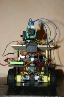
In addition, this camera is mounted on a Tilt&Pan driven by 2 servos in order to allow horizontal and vertical moves.
The connectivity between the Camera and the ChipKit is the following:
/* Camera *//* UART2 interface is provided on pins: *//* 1 = Power +5V *//* 2 = TX connected to J4-04 (AETXD1/SCK1A/U1BTX/U1ARTS/CN21/RD15)*//* 3 = RX connected to J4-03 (AETXD0/SS1A/U1BRX/U1ACTS/CN20/RD14) *//* 4 = Ground */
Tilt&Pan Servos
The camera is mounted on a Tilt&Pan driven by 2 servos in order to allow horizontal and vertical moves.
These servos are managed like the IR servo.
The connectivity between the Tilt&Pan Servos and the ChipKit is the following:
#define HSERVO_Pin 34 // Horizontal Servo pin connected to digital pin J9-04 (PMD3/RE3)/* Power +5V *//* Ground */#define VSERVO_Pin 35 // Vertical Servo pin connected to digital pin J9-03 (PMD2/RE2)/* Power +5V *//* Ground */ Here you can see the camera mounted on the Titl&Pan and the IR sensor.
SD Card
SD card is used to store the images taken by the camera.
The SD Card communicates with the PIC via the SPI interface.
WARNING: there is a conflict using SD-Card and WIFI as described by KeithV from Diligent. The problem is the Wi-Fi and SD both share the same SPI port and the Wi-Fi module responds to INT1 on the WiFiShield. If you are reading the SD card when the Wi-Fi gets an interrupt, the PIC will CS the Wi-Fi module and both the SD and Wi-Fi SPI devices will be selected and corruption occurs. Following the proposal of KeithV, I have updated the standard SD Card lib in order to disable INT1 while reading/writing the SD card.
Communication
The robot can communicate using XBee or WIFI.
I have written a small Java interface in order to communicate with the robot allowing both protocols but only one mode is available at one time because it depends on the shield plugged to the main ChipKIT Board.
XBee Communication
WIFI Communication
I use the ChipKit Wi-Fi Shield™ which is based on the Microchip MRF24WB0MA Wi-Fi module.
It communicates with the PIC via SPI and it uses also INT1 (warning refer Conflict in SD Card section).
It is intended for use with the Digilent network libraries, DNETcK and DWIFIcK. Be careful because these lib are huge (60K), it is the reason why I have migrate from Uno to Max.
I have used these libs to build a mini HTTP server that listens to one port and establishes a connection if a client tries to connect. Then the message received is parsed in order to determine which command is required and the optional parameters. I have defined the following format for the message:
CMD=command&PARAM=param1;param2;where command is the command required and param1, param 2.. are the optional parameters with” ;” as separator. CMD and PARAM are the two keywords.
Once the command is processed by the robot, it answers with the following format (Content-Type: text/html):
Field 0:value0; Field 1:value1;where value0, value1 are the optional answers with” ;” as separator. Field is keyword.
In case of command that triggers a picture, the answer is composed of the stream of bytes (Content-Type: application/octet-stream) that represent the content of the JPEG file.
Contactors
The first tests with only the IR sensor as barrier detector highlighted some limitations, for example the small barriers on the ground are not detected.
So I have added 2 contactors with « mustach » that signal the contact with an barrier.
The principle is simple, as soon as the contactor hits an barrier, its pin Signal goes from high to low level.
So I have added in the function in charge of the barrier detection the check of the state of the contactor pins mounted at the left and right fronts of the robot.
But at the opposite of the IR sensor that can detect the barriers at a defined distance, the contactors detect only at the latest time.
This double detection decreases the risk missing barrier detection.
The connectivity between the contactors and the ChipKit is the following:
#define ContactRightPin 37 // Contact sensor Right pin connected to digital pin J9-01 (PMD0/RE0)
#define ContactLeftPin 38 // Contact sensor Left pin connected to digital pin J8-18 (SCK1/IC3/PMCS2/PMA15/RD10)
LCD screen
The robot sends information via WIFI or XBee which is available on the PC, but it is also useful to know what is happening directly on the robot.
It is for this reason that I added an LCD screen on which I display all commands executed by the robot, information and the errors encountered.
The disadvantage of LCD is that usually they monopolize many pins to communicate with the micro-controller, but fortunately some boards combine a LCD with an interface module with an I2C bus, in this case the LCD has no pin dedicated.
So I set up a board I2C/TWI LCD1602 LCD based on the LCD HD44780U and driven by the LiquidCrystal_I2C library. The LCD displays two lines of 16 characters 5 * 7 pixels. It also allows you to define custom 7 characters. I control the screen by managing via the I2C protocol the values of the register of the LCD screen.
The I2C address is defined as follow:
LiquidCrystal_I2C lcd(0x20,16,2); // set the LCD address to 0x20 for a 16 chars and 2 line display
You can read a more detailed description of the LCD screen functionalities in this document.
Refer to the previous Compass section for the details regarding the I2C connection.
Here you can see the LCD screen:
Buzzer
I have added also a buzzer that buzzes in certain situations: end of initialization, detection of barrier, error.
It works very simply as it needs only to be activated during a short period with a digital output.
The connectivity between the buzzer and the ChipKit is the following:
#define buzzPin 39 // Buzzer connected to digital pin J8-15(PMRD/CN14/RD5)
Motors control
I have written a lib that manage the speed of the 4 motors using the encoders, the direction using the Compass and detects the barriers using the IR sensor mounted on a servo.
The functions of the lib are the following:
void IntrTickRight(); interrupt handler encodeur right
void IntrTickLeft(); interrupt handler encodeur right
int motor_begin(); initialize everything, must be called during setup
int get_TickRight (); get Tick Right
int get_TickLeft(); get Tick Left
int get_SpeedMotorRight(); get Speed Motor Right
int get_SpeedMotorLeft(); get Speed Motor Left
void forward_test(int num); set IN of the motor num in order to run clockwise
void start_forward(); call forward + set enable pin of the 4 motors to SPEEDNOMINAL
void start_forward_test(int num); call forward + set enable pin of the motor num to SPEEDNOMINAL
void backward(); set IN of the 4 motors in order to run anti-clockwise
void start_backward(); call backward +set enable pin of the 4 motors to SPEEDNOMINAL
void stop(); set IN of the 4 motors in order to stop
int accelerate (int motor); set enable pin of the corresponding motors to an higher value (1 increment)
int accelerate_n (int motor, int n); set enable pin of the corresponding motors to an higher value (n increments)
int deccelerate(int motor); set enable pin of the corresponding motors to a lower value
(1 decrement)
int deccelerate_n(int motor, int n); set enable pin of the corresponding motors to a lower value (n decrements)
int adjustMotor (int motor, int pid); Adjust the speed of the motor according the PID value
int go(int d, int pid_ind); go during d encoder ticks or before in case of barrier detected by IR sensor. if pid_ind = 1 then use a PID method (calling adjustMotor) to control motors speed between left and right
int check_around(); move the servo used by the IR sensor in order to determine the direction without barrier
int turn(double alpha, unsigned long timeout); turns with an angle before a delay (timeout) using a compass to get the direction
Robot control
I have developed a Java application with Eclipse, it can send commands to the robot and display information from the robot.
As described earlier, it can use WiFi or XBee communication.
The available commands are:
START: Start the robot forward at cruise speed, cancels any previous GO command.
STOP: Stops the robot, cancels any previous GO command.
INFO: Retrieves information of the robot status Start / Stop, theoretical speed, actual speed, temperature, distance barrier, direction.
PICTURE: Ask the robot to take a picture, to store it on the SD card and to return it by WIFI or XBee, the robot is stopped for the photo.
TURN_RIGHT + angle: Ask the robot to turn right at an angle. If this angle = 180, then the robot changes direction.
TURN_LEFT+ angle: Ask the robot to turn left at an angle. If this angle = 180, then the robot changes direction.
CHECK_AROUND: Ask the robot to determine the direction without barrier (front, left or right)
MOVE_TILT_PAN + angle1 + angle2: Ask the robot to move the Pan & Tilt of the camera according to the angles of horizontal and vertical deflection.
GO + time: Start the robot forward at cruise speed then let it autonomous for a while.
Sources
The sources of the Java application used to command the robot
Core resources
In order to avoid any conflicts between the components of the Robot, it is important to known in detail which core resource is used by each component.
Here is the summary including some details about the use of the core resources:
Enable 4 motors (analogwrite)
***********************************
use TMR2 and TIMER_OC1,TIMER_OC2, TIMER_OC3, TIMER_OC4, TIMER_OC5 to generate PWM
// If no PWM are currently active, then init Timer2
if (pwm_active == 0)
{
T2CON = T2_PS_1_256;
TMR2 = 0;
PR2 = PWM_TIMER_PERIOD;
T2CONSET = T2_ON;
}
//generate bit mask for this output compare
//should assert(timer < 8) here, but assertions aren't being used
pwm_mask = (1 << (timer - _TIMER_OC1));
//Obtain a pointer to the output compare being being used
//NOTE: as of 11/15/2011 All existing PIC32 devices
// (PIC32MX1XX/2XX/3XX/4XX/5XX/6XX/7XX) have the output compares
// at the same addresses. The base address is _OCMP1_BASE_ADDRESS
// and the distance between their addresses is 0x200.
ocp = (p32_oc *)(_OCMP1_BASE_ADDRESS + (0x200 * (timer - _TIMER_OC1)));
// If the requested PWM isn't active, init its output compare
if ((pwm_active & pwm_mask) == 0)
{
ocp->ocxR.reg = ((PWM_TIMER_PERIOD*val)/256);
ocp->ocxCon.reg = OC_TIMER2_SRC | OC_PWM_FAULT_PIN_DISABLE;
ocp->ocxCon.set = OC_ON;
pwm_active |= pwm_mask;
}
// Set the duty cycle register for the requested output compare
ocp->ocxRs.reg = ((PWM_TIMER_PERIOD*val)/256);
Encoders 2 motors
**********************
use interrupts INT3 and INT4
IEC0bits.INT3IE = 0;
IFS0bits.INT3IF = 0;
INTCONbits.INT3EP = edge;
IPC3bits.INT3IP = _INT3_IPL_IPC;
IPC3bits.INT3IS = _INT3_SPL_IPC;
IEC0bits.INT3IE = 1;
IEC0bits.INT4IE = 0;
IFS0bits.INT4IF = 0;
INTCONbits.INT4EP = edge;
IPC4bits.INT4IP = _INT4_IPL_IPC;
IPC4bits.INT4IS = _INT4_SPL_IPC;
IEC0bits.INT4IE = 1;
IR sensor
*************
use ADC module channel 2
/* Ensure that the pin associated with the analog channel is in analog
** input mode, and select the channel in the input mux.
*/
AD1PCFG = ~(1 << channelNumber);
AD1CHS = (channelNumber & 0xFFFF) << 16;
AD1CON1 = 0; //Ends sampling, and starts converting
//Set up for manual sampling
AD1CSSL = 0;
AD1CON3 = 0x0002; //Tad = internal 6 Tpb
AD1CON2 = analog_reference;
//Turn on ADC
AD1CON1SET = 0x8000;
//Start sampling
AD1CON1SET = 0x0002;
//Delay for a bit
delayMicroseconds(2);
//Start conversion
AD1CON1CLR = 0x0002;
//Wait for conversion to finish
while (!(AD1CON1 & 0x0001));
//Read the ADC Value
analogValue = ADC1BUF0
Compas
**********
use I2C module #5
Servos
********
use TIMER4 to create pulse
//timer 4 set clock period 20ms
T4CON = 0x0060; // set prescalar 1:64
TMR4 = 0;
PR4 = 0x61A8;
IFS0CLR = 0x10000;// Clear the T4 interrupt flag
IEC0SET = 0x10000;// Enable T4 interrupt
IPC4CLR = 0x0000001F;
IPC4SET = (_T4_IPL_IPC << 2) | _T4_SPL_IPC;
T4CONSET = 0x8000;// Enable Timer4
Xbee
******
use UART1 as the USB-PC connection
p32_regset * ipc; //interrupt priority control register set
int irq_shift;
/* Initialize the receive buffer.
*/
flush();
/* Compute the address of the interrupt priority control
** registers used by this UART
*/
ipc = ((p32_regset *)&IPC0) + (vec / 4); //interrupt priority control reg set
/* Compute the number of bit positions to shift to get to the
** correct position for the priority bits for this IRQ.
*/
irq_shift = 8 * (vec % 4);
/* Set the interrupt privilege level and sub-privilege level
*/
ipc->clr = (0x1F << irq_shift);
ipc->set = ((ipl << 2) + spl) << irq_shift;
/* Clear the interrupt flags, and set the interrupt enables for the
** interrupts used by this UART.
*/
ifs->clr = bit_rx + bit_tx + bit_err; //clear all interrupt flags
iec->clr = bit_rx + bit_tx + bit_err; //disable all interrupts
iec->set = bit_rx; //enable rx interrupts
/* Initialize the UART itself.
*/
// http://www.chipkit.org/forum/viewtopic.php?f=7&t=213&p=948#p948
uart->uxBrg.reg = ((__PIC32_pbClk / 16 / baudRate) - 1); // calculate actual BAUD generate value.
uart->uxSta.reg = 0;
uart->uxMode.reg = (1 << _UARTMODE_ON); //enable UART module
uart->uxSta.reg = (1 << _UARTSTA_UTXEN) + (1 << _UARTSTA_URXEN); //enable transmitter and receiver
Camera
*********
use UART2
p32_regset * ipc; //interrupt priority control register set
int irq_shift;
/* Initialize the receive buffer.
*/
flush();
/* Compute the address of the interrupt priority control
** registers used by this UART
*/
ipc = ((p32_regset *)&IPC0) + (vec / 4); //interrupt priority control reg set
/* Compute the number of bit positions to shift to get to the
** correct position for the priority bits for this IRQ.
*/
irq_shift = 8 * (vec % 4);
/* Set the interrupt privilege level and sub-privilege level
*/
ipc->clr = (0x1F << irq_shift);
ipc->set = ((ipl << 2) + spl) << irq_shift;
/* Clear the interrupt flags, and set the interrupt enables for the
** interrupts used by this UART.
*/
ifs->clr = bit_rx + bit_tx + bit_err; //clear all interrupt flags
iec->clr = bit_rx + bit_tx + bit_err; //disable all interrupts
iec->set = bit_rx; //enable rx interrupts
/* Initialize the UART itself.
*/
// http://www.chipkit.org/forum/viewtopic.php?f=7&t=213&p=948#p948
uart->uxBrg.reg = ((__PIC32_pbClk / 16 / baudRate) - 1); // calculate actual BAUD generate value.
uart->uxSta.reg = 0;
uart->uxMode.reg = (1 << _UARTMODE_ON); //enable UART module
uart->uxSta.reg = (1 << _UARTSTA_UTXEN) + (1 << _UARTSTA_URXEN); //enable transmitter and receiver
SD-Card
**********
use SPI module and pin 4 for SS/CS
SPI2CON = 0;
DDPCONbits.JTAGEN = 0;
AD1PCFG = 0xFFFF;
chipSelectPin_ = chipSelectPin;
pinMode(chipSelectPin_, OUTPUT);
PORTSetPinsDigitalOut(prtSCK, bnSCK);
PORTSetPinsDigitalOut(prtSDO, bnSDO);
PORTSetPinsDigitalIn(prtSDI, bnSDI);
// set pin modes
chipSelectHigh();
// must supply min of 74 clock cycles with CS high.
for (uint8_t i = 0; i < 10; i++) spiSend(0XFF);
chipSelectLow();
// command to go idle in SPI mode
while ((status_ = cardCommand(CMD0, 0)) != R1_IDLE_STATE) {
if (((uint16_t)millis() - t0) > SD_INIT_TIMEOUT) {
error(SD_CARD_ERROR_CMD0);
goto fail;
}
}
// check SD version
if ((cardCommand(CMD8, 0x1AA) & R1_ILLEGAL_COMMAND)) {
type(SD_CARD_TYPE_SD1);
} else {
// only need last byte of r7 response
for (uint8_t i = 0; i < 4; i++) {
status_ = spiRec();
}
if (status_ != 0XAA) {
error(SD_CARD_ERROR_CMD8);
goto fail;
}
type(SD_CARD_TYPE_SD2);
}
// initialize card and send host supports SDHC if SD2
arg = type() == SD_CARD_TYPE_SD2 ? 0X40000000 : 0;
while ((status_ = cardAcmd(ACMD41, arg)) != R1_READY_STATE) {
// check for timeout
if (((uint16_t)millis() - t0) > SD_INIT_TIMEOUT) {
error(SD_CARD_ERROR_ACMD41);
goto fail;
}
}
// if SD2 read OCR register to check for SDHC card
if (type() == SD_CARD_TYPE_SD2) {
if (cardCommand(CMD58, 0)) {
error(SD_CARD_ERROR_CMD58);
goto fail;
}
if ((spiRec() & 0XC0) == 0XC0) {
type(SD_CARD_TYPE_SDHC);
}
// discard rest of ocr - contains allowed voltage range
for (uint8_t i = 0; i < 3; i++) spiRec();
}
chipSelectHigh();
WIFI
******
use SPI module and pin 10 for SS/CS + INT1
Robot camera controlled by Wifi/Xbee or stand-alone
- Actuators / output devices: L298 motor controller, encoder wheels, DFRobot motors
- Control method: Wifi connection to Internet, Xbee Wireless remote control
- CPU: PIC32MX795F512L
- Power source: 7.4V 350mAh LiPo
- Programming language: C++, Java, C
- Sensors / input devices: Sharp IR, two front bumper switches, camera, CMPS03 digital compass, LCD