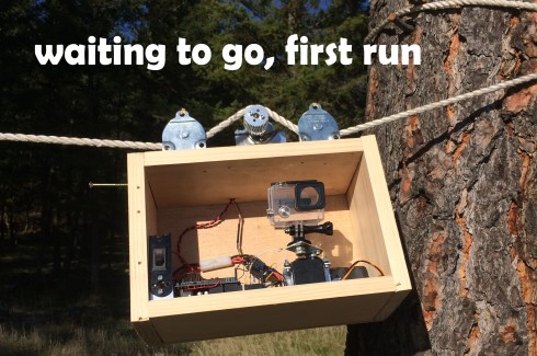
Moving time-lapse rig
Edit, voting is over.
HEY LMR I FOUND OUT I AM IN 6TH, I NEED TO MAKE IT TO 5TH TO BE CONSIDERED FOR JUDGING, HERE IS THE LIKE PLEASE VOTE http://shar.es/Voz4W !!!
Hey LMR This is a rig that I made to move my gopro along a rope to create a moving time-lapse effect.
It was a weekend project that I made as an entry for the 'Make the shot camera challenge'. If any fellow LMR members here like this project and would like to support a fellow LMR member, I would appreciate a vote at the challenge. http://shar.es/STAUV Voting is open worldwide last I checked.
Description: After seeing the cool possibilities of moving time-lapse photography, I decided to make a device that allowed me to do this myself. The device had to be capable of moving a camera along a path, at a relatively constant speed.
After researching these rigs on the Internet, I noticed that many were made out of large, bulky, slider systems. Linear rails are good at providing smooth motion over their range and will produce good quality results. However, I didn't want to go this route. This posed many challenges for me: 1) expensive: linear sliders, especially quality ones tend to be quite pricy. 2) They not very portable: I enjoy experiencing the outdoors; therefore I want a system that I can take with me easily.
With these constraints in mind I came up with the idea of making a time-lapse fixture that operated by moving across a rope. Let me explain: A rope is easy to tie between two objects; for instance when camping two trees will suffice. I can then make a pulley mounted fixture that has a motor that moves across the rope. This was a simple process that involved commonly available parts; furthermore it was not very expensive.
Read below for my build process.
For the first use I set up the device between two trees and attached a Go Pro. The rope had a clip on one end allowing me to simply loop it around the tree and clip it on. On the other side I pulled the rope tight and wrapped it around the tree a few times before tying a little knot. After attaching the gopro I used its nifty little time-lapse mode, set it to 10 seconds between pictures and started it. I then hit the go button on the Arduino and after a second survey of the area to check and make sure everything was working I left. After many hours I returned and took down the whole setup. Using Go Pro Studio (free on their website) I was able to stitch the images together and produce the time-lapse.
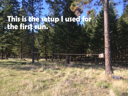
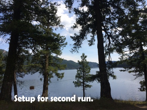
Conclusion: This was a great weekend project for me, I would think it would be for anyone else who is interesting in time-lapse photography and would like a nice little addition to their toolset. Even without using a GoPro like I did, most modern smart-phones have apps that you can get for free that will do time-lapses. As anyone who designs things knows it is often a process of trial and error. Given the time constraints imposed by this project I didn’t do any advanced CAD or electrical design. For a next version in the future I could easily see myself building a much more compact version that would be 3-D printed.
Assembly Instructions: This is a nice weekend project: I started by determining what I would need. These included: motor w/ encoder, motor controller, Arduino, LCD shield, battery, pulleys, rope, various hardware and wire. All of this I already had around the workbench save the pulleys. Thus before I began I ran to Lowes and purchased two pulleys. I found ones that were designed for direct mounting ,which was nice.
To begin I designed the pulley system: On a wood board I mounted a motor and two pulleys. While not the best mechanical system my setup worked. I found that if I got the rope decently tight but not super tight the gears would have sufficient traction to move along the rope while not putting overbearing stress on the motor.
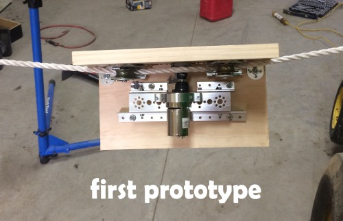
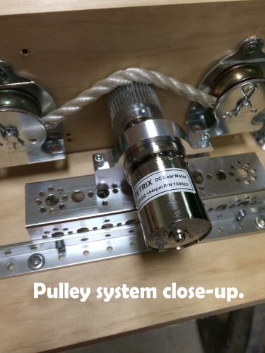
Once I had a decent mounting system the electronics to drive it was next. While there are cheaper ways to do this I was using parts that I already had so my setup was a bit of overkill. I used a Saber tooth 2x25 motor controller this was hooked to a 12 volt 3 amp hour battery (through a fuse and switch of course ;-) ). This worked but any 5-10amp motor controller will do and the battery need not be that big. For control I wired the motor controller as well as the encoder attached to the motor to an Arduino mega with LCD keypad shield I had on hand. The LCD shield is nice to attach to any project to have a good idea of what it is doing.
This left programming to be completed. Being a weekend project I threw together a quick sketch that would control how far and how fast the device went. I used the Arduino encoder, LCD and servo libraries. These are all open source. I uploaded the code onto Github if anyone else is building one of these and wants a reference.
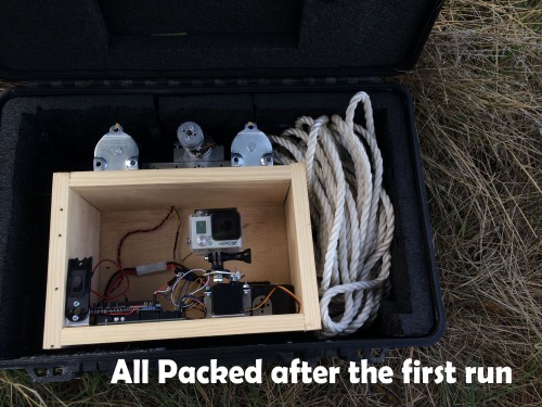
move along a rope and take pictures


