


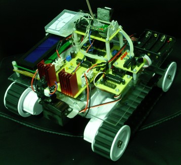
modullo [Modular Robotic Platform]
This is modullo, one of my first elaborated robotic platforms. It hasn't got an actual purpose yet, I'm at the stage of adding various sensors and integrating them into a functional system.
The main design of the platform revolves around the concept of modularity. Each function of the robot is being taken care of by a separate microcontroller, while the main microcontroller, the ATMega16 (which is going to be replaced with an Digilent Nexys 2 FPGA when more processing power would be needed) communicates serially with each of the "peripherals" and processes all the inputs and outputs according to its final purpose.
The development platform is a Dagu Rover 5 tracked platform, which has 4 motors and 4 wheel encoders. The torque developed by the motors is enormous, the tracks are very grippy and the quadrature encoders offer 333 steps / revolution. It has some flaws, such as the fact that the current limiting of the IR LEDs of the wheel encoders is too low and the 1K resistor had to be replaced with a 500ohm resistor (or by 2 parallel 1K resistors) in order for the encoders to work properly. Another flaw would be the fact that the tracks occasionally come off when the platform rotates around its axis on a rough surface. All in all, it's a very good platform for its value.
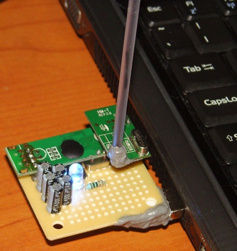
All the microcontrollers are being programmed using the BASCOM AVR 1.11.9.0 IDE, a home-made USBTiny programmer that uses an ATTiny2313 microcontroller and, of course, the already popular AVRDude programming tool.
Now I will briefly describe the modules installed at the moment on the platform.
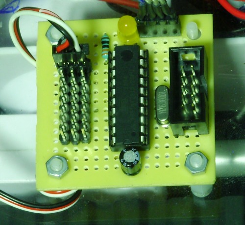
1. The main board - using an ATMega16 microcontroller, running at 16 MHz
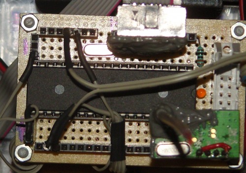
The main board sends and receives serial data to/from the other boards, along with receiving serial data from the radio module. The communication with the peripheral boards is done at a baud rate of 57600 bps and triggered by interrupts corresponding to each board. The main board triggers the interrupts, while each peripheral board sends/receives the data when the interrupt is triggered. The UART used for communicating with the peripherals is software (emulated), not hardware. The hardware channel is used for receiving data from the radio module (and, after further development, for sending back data to a master computer). The speed of radio communication is 4800 bps, quite slow, but the only option with the current modules. They also work at a baud rate of 9600 bps, but their range and sensitivity is greatly empaired.
This board will be, at some point, replaced by a Digilent Nexys 2 FPGA, which provides a far greater memory and processing speed, along with more than 100 input/output ports. All this processing power comes with the cost of a more complicated but cleaner and more popular programming language, the VHDL.
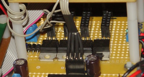
2. The motor controller - using an ATTiny2313 microcontroller, running at 16 MHz and 2x L298 motor drivers
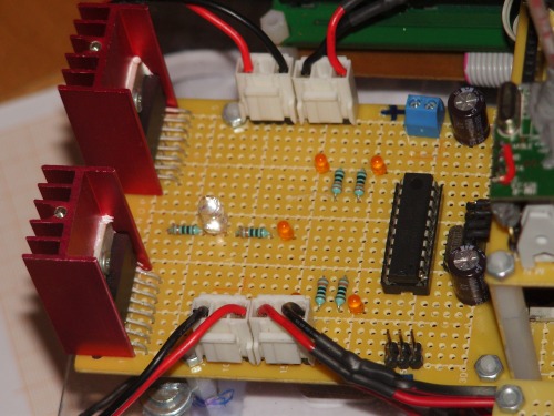
The motor controller board microcontroller receives two bytes of data, one for each motor. It computes the PWM timing values and the direction bit and sends the output to each of the two L298 motor drivers. The PWM is, again, emulated, at a frequency of ~1 kHz. The chosen frequency is arbitrary, but it has lead to good results so far. Each L298 motor driver is able to drive two motors, so each L298 driver is used for a pair of motors on each side of the robot. There are also some indicator LEDs on the motor controller board: 4 of them are driven by the same PWM signals that drive the L298 drivers, while one of them blinks at each new data set received from the main board. Another LED indicates that the H-Bridges inside the L298 drivers are powered.
3. The power unit
It is basically a bunch of linear voltage regulators. There are 3x LM7805 5V regulators and one TS1086 3.3V regulator along with some failsafe diodes and an indicator LED. The 5V regulators power the microcontrollers, while the 3.3V regulator is used by some sensors, such as accelerometers or gyroscopes, that require this voltage. I used 3x 5V regulators because they tend to overheat even when used at low currents, so by splitting the total drawn current through 3 separate regulators, this minor problem can be neglected.
4. The battery charge level display - using an ATMega8 microcontroller, running at 12 MHz

This unit is being connected directly to the battery pack and it has its own LM7805 regulator. As the voltage provided by the Ni-Mh battery pack floats between a value over 8.4V when fully charged and 6V when fully discharged, the voltage across the battery pack is splitted over a voltage divider before being read by the ATMega8 on one of its ADC channels. The ADC value, corresponding to half of the battery pack voltage, is compared to the values corresponding to the fully charged / fully discharged and 6 intermediate intervals. The charge level is displayed using 8 LEDs which light up corresponding to the charge level. When it is fully charged, all the 8 LEDs are lit and when it's fully discharged, only the last LED is lit. The charge capacity is, of course, not a linear function of the output voltage, but a rough estimation of the charge level can be easily provided by the unit.
UPDATE: I have replaced the battery meter unit with an analogue 0-15V DC voltage meter. This unit will be replaced later on with another one based on an ATTiny26 or even ATTiny25/ATTiny13 microcontroller and some low-power LEDs (probably SMD).
5. The motor encoder manager - using an ATTiny2313 microcontroller, running at 16 MHz
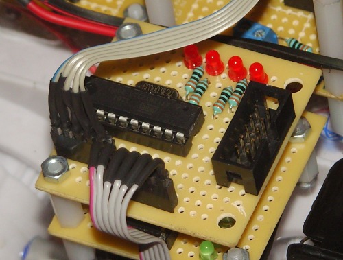
This unit reads the inputs from two of the wheel encoders (one on each side). The microcontroller reads the quadrature grey code, computes the direction of rotation (displayed using 2 of the 4 LEDs for each side), measures the interval spent between two rotational steps for each side and then sends all the information serially to the main board. The main microcontroller will recalculate, using a PID algorithm, the command bytes that are being sent to the motor controller board so that the robot moves as it is supposed to. It will also send back to the computer all the information so that I could trace the route of the robot. This board is still under development, along with the PID algorithm needed for precisely controlling the speed and direction of the robot.
Update: I'm having a hard time dealing with the wheel encoders and with the PID algorithm. I managed to process the encoder informations, but the PID constants are still a mistery and the robot handles a bit weirdly. Working on it.
6. The USB Remote - using a PL2303 USB-Serial converter, a MAX232 level shifter and a 868 MHz radio module
The USB Remote is a small device plugged into any USB port of the computer and that allows the robot to be remotely controlled using a computer. The data sent via the USB port is converted to a RS232 signal, then to a 5V TTL UART signal that is being fed to the radio module. The PL2303 USB-Serial converter requires no special driver. I should mention that I'm using Ubuntu for all the robotic applications. At the moment, the protocol used by the remote allows the control of the robotic platform motors with a precision of 8-bit (7-bit per direction + direction bit), 4 additional 8-bit channels for various proportional-movement components, such as servos and 8 digital channels for triggering various devices. The software used for actually controlling the robot through the remote is developed using the SFML C++ library and the Code::Blocks 10.05 IDE.
7. The 8-channel servo controller - using an ATTiny2313 microcontroller, running at 16 MHz
The unit receives 8 bytes from the master unit, each corresponding to a separate servo channel. Then, the software computes the time variables for each servo channel and generates the PWM signal for controlling the servos. There are two additional 47 uF capacitors on the board, because of the noise generated by the electric motors inside the servos. For the moment, the unit is only used for controlling the servo used for detecting front obstacles. Later on, the detector will be used to do a proper mapping of the surroundings.
ADDITIONAL COMPONENTS:
1. The IR Radar system - using a Futaba S3003 servo and a Sharp GP2Y0A21YK0F IR sensor (10-80 cm range)
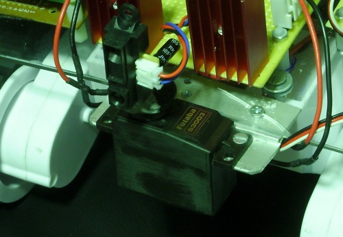
For the moment, the radar-like system is used for detecting front obstacles. It sweeps between 3 positions (-45 deg, center, +45 deg) and detects any forward obstacles. Later on, the radar will be used to sweep a complete half-circle area in front of the robot in order to create a map. The output of the Sharp IR sensor is fed directly to one of the ADC channels of the main board.
I also use a 4x20 LCD display, connected to the main board. Its main purpose is debugging and it will mostly likely be taken off the robot when its development ends. At the moment, it displays the values of the motor command bytes received from the computer.
Feel free to post comments concerning my project, to give me feedback and ideas or to ask me further details.
02-Oct-2011 --- UPDATE --- New level installed :D
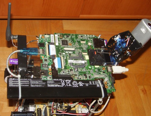
About a week ago, I bought an Asus eeePC 1001px motherboard and an appropriate 6-cell battery that will further represent the brain of modullo. I installed xUbuntu 10.04 on an 8GB USB memory stick and stripped down all the useless applications. For now, the OS uses about 3 GB, leaving about 5 free GB of space. All the developed software is saved on a 2 GB SD Card, so that I could reinstall/change the OS after a while with no complications. This new module, the eeepc, is placed on top of the robot, leaving plenty of room underneath for easily accessing the electronics. Later on, I will provide it with a nice housing and it will be placed as low as possible, so that the total height of the robot will be as small as possible. Of course, I needed an USB hub as the motherboard only had 2 USB ports. When the robot is in the "development mode", both the mouse and keyboard are connected on USB ports, along with the memory stick and the type-B USB cable that provides the communication with the ATMega16 microcontroller.
The main reason for which I used a computer on the robot would be the advantage offered by the flawless WLAN or even Mobile Internet bidirectional data transfer. No more package losses, no more interference and neglictible lag (as I used UDP instead of TCP/IP). I used the SFML library for communicating (for the moment, only for that) with the master eeePC (a trusty 1005p that I used almost daily at the university last year) and the RS-232 library for the USB - ATMEL communication. I "upgraded" to a proper library instead of communicating using more-or-less appropriate stdio functions because it provides clear and simple to use functions.
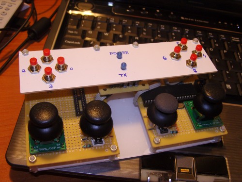
In order to control the robot, I use an USB remote control, having 8 2-axis analog sticks and 8 pushbuttons. Its brain is an ATMega8535 microcontroller (one of the oldest I have around), which reads the ADC values from the analog sticks and the digital inputs from the buttons, encodes the values into a data stream and sends it to the computer via a MAX232 level shifter and a HL-340 USB-serial adapter. The master application (on the master netbook) reads the values and forwards them via LAN/WLAN (using an UDP protocol) to the robot's computer. The robot's computer slave software reads the received data and computes the data stream that is sent to the robot. After I add some more sensors to the robot, the data read from them will be sent back to the master netbook. As you can see, the remote still needs a proper housing.
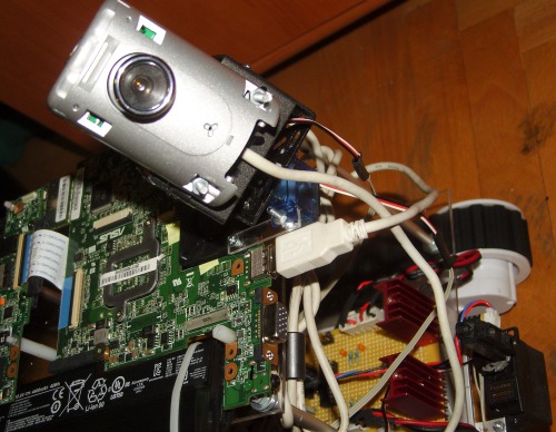
I also added a webcam mounted on a Dagu Pan/Tilt kit. Unfortunately, the micro sensors are not strong enough for the weight of the webcam (the kit was designed for sensors, so no wonder why). I'll either change the webcam with a smaller one (for the moment, this is the only I have around), or replace the servos with a pair of Futaba S3003 standard servos. Or both, as the webcam is large anyway and the servos lack precision.
So, for the moment the robot is able to be remotely controlled via WLAN, reads some encoder values and has a Sharp sensor that sweeps the area in front of the robot. The next steps would be sending all the information read by the robot back to the master computer (and use them in an useful way), add more sensors, improve the precision of the robot and develop a very user-friendly GUI for the master netbook (using, of course, the same SFML library and some of my old Photoshopping skills). Then maybe I'll have time to work on the exterior design (a housing for the robot and the remote).
- Actuators / output devices: Dagu Rover 5 tracked platform (4 motors + 4 encoders)
- Control method: WLAN peer-to-peer
- CPU: ATmega16, 3x ATTiny2313, Intel Atom N450
- Operating system: xUbuntu 10.04 LTS
- Power source: 9.6V Sanyo Eneloop XX (2500 mAh)
- Programming language: C++, Basic
- Sensors / input devices: 333 steps/rotation encoders
- Target environment: indoor, outdoor