Mobile robot -- Dzik Rover
Intro
Hello to everyone :) I'm Łukasz and I want to share with you the process of design and building my robot Dzik Rover. It's my very first project, therefore some things in it I had to do a couple of times :P just a trial and error method until I get fine solution of the problem.
Project was divide on stages:
- searching for the right parts and design mechanical part by Autodesk Inventor 2016
- workshop work on mechanincal construction part of the project
- design PCB board by Autdesk Eagle
- workshop work on electronic and electric part of the project
- write basic software which allowing to control robot from PC level
- tests
Additional link:
- https://grabcad.com/library/dzik-rover-1
- https://github.com/elektronicznyJuzek/Dzik_Rover
- https://photos.app.goo.gl/5BeGHkzRw9LUZSff1
Specs:
- dimensions(w,l,h):
- 300x400x160 mm, box
- 550x530x300 mm, box with wheels - weight: 11 kg
- control method: manual via WiFi
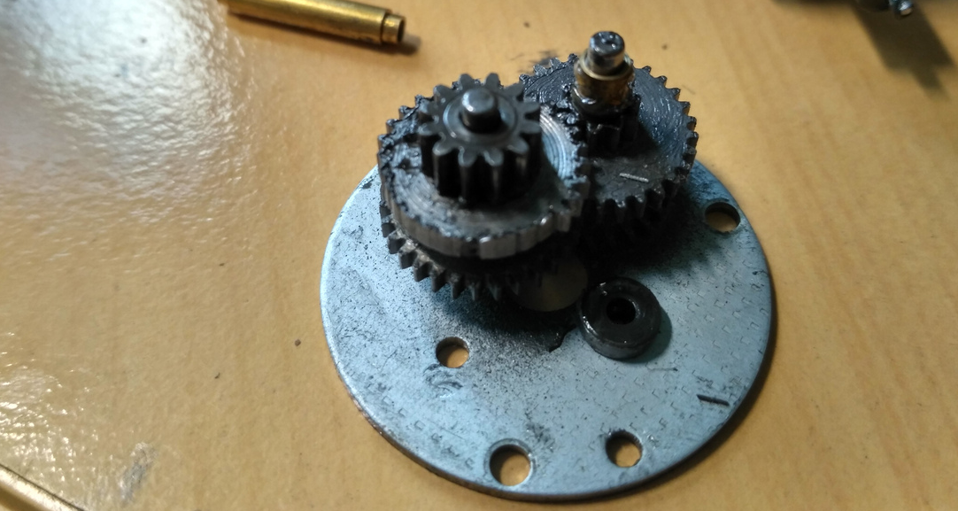
- actuators: 4 DC motors with metal gear
- CPU: Raspberry Pi 3b, Atmega328P
- power source: 18650 packets: 2x 4S2P for motors, 1x 2S4P for logic
- programming language: C/C++
Mechanical part
- 4 whell drive
- independent suspensio
- bearing axles
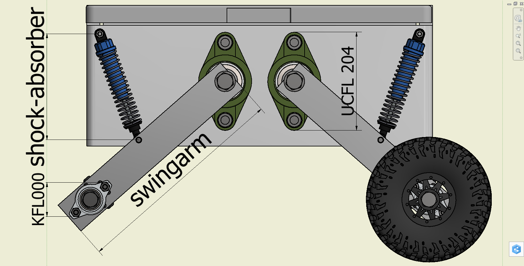
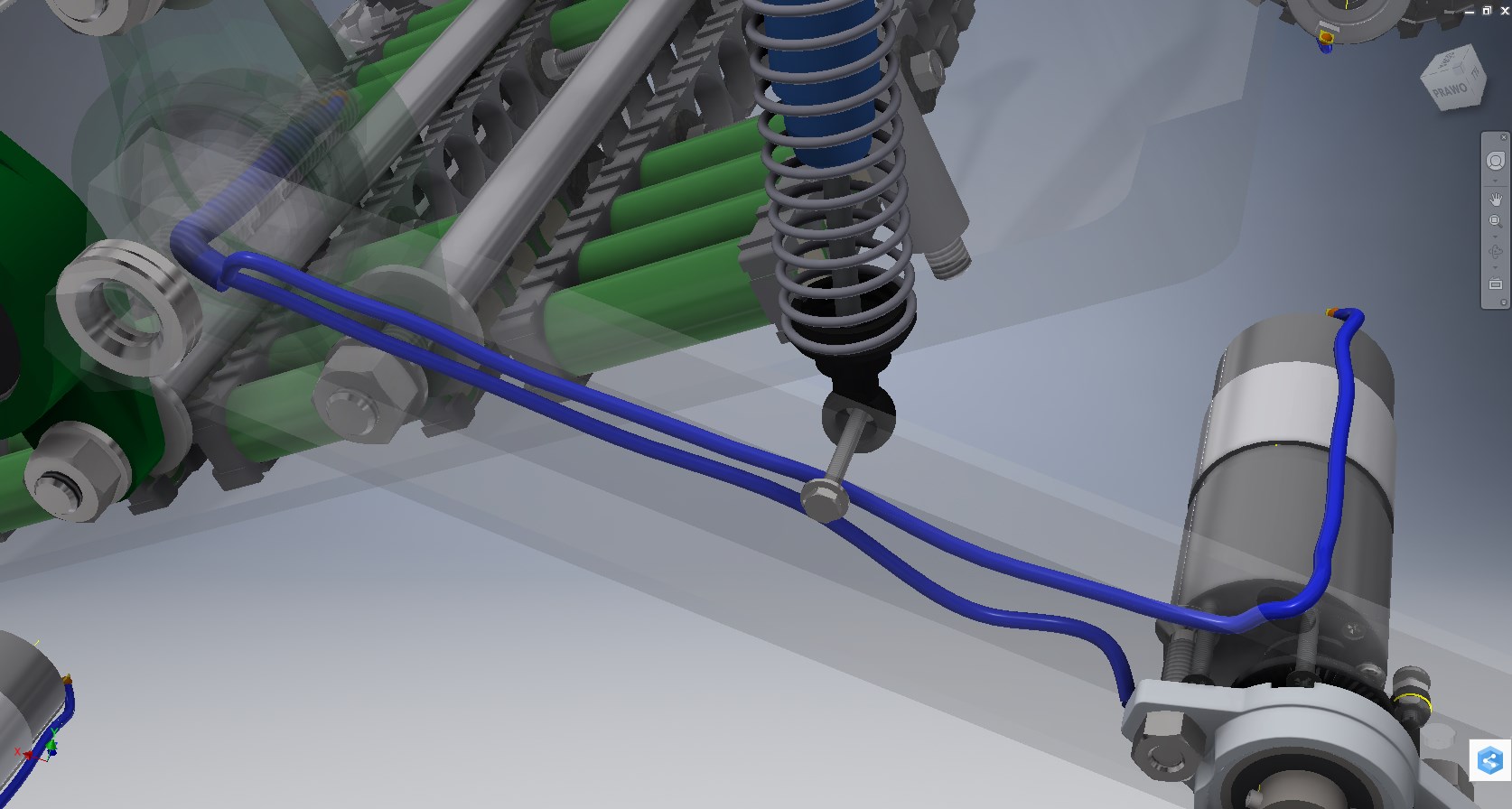
scheme of the suspension system
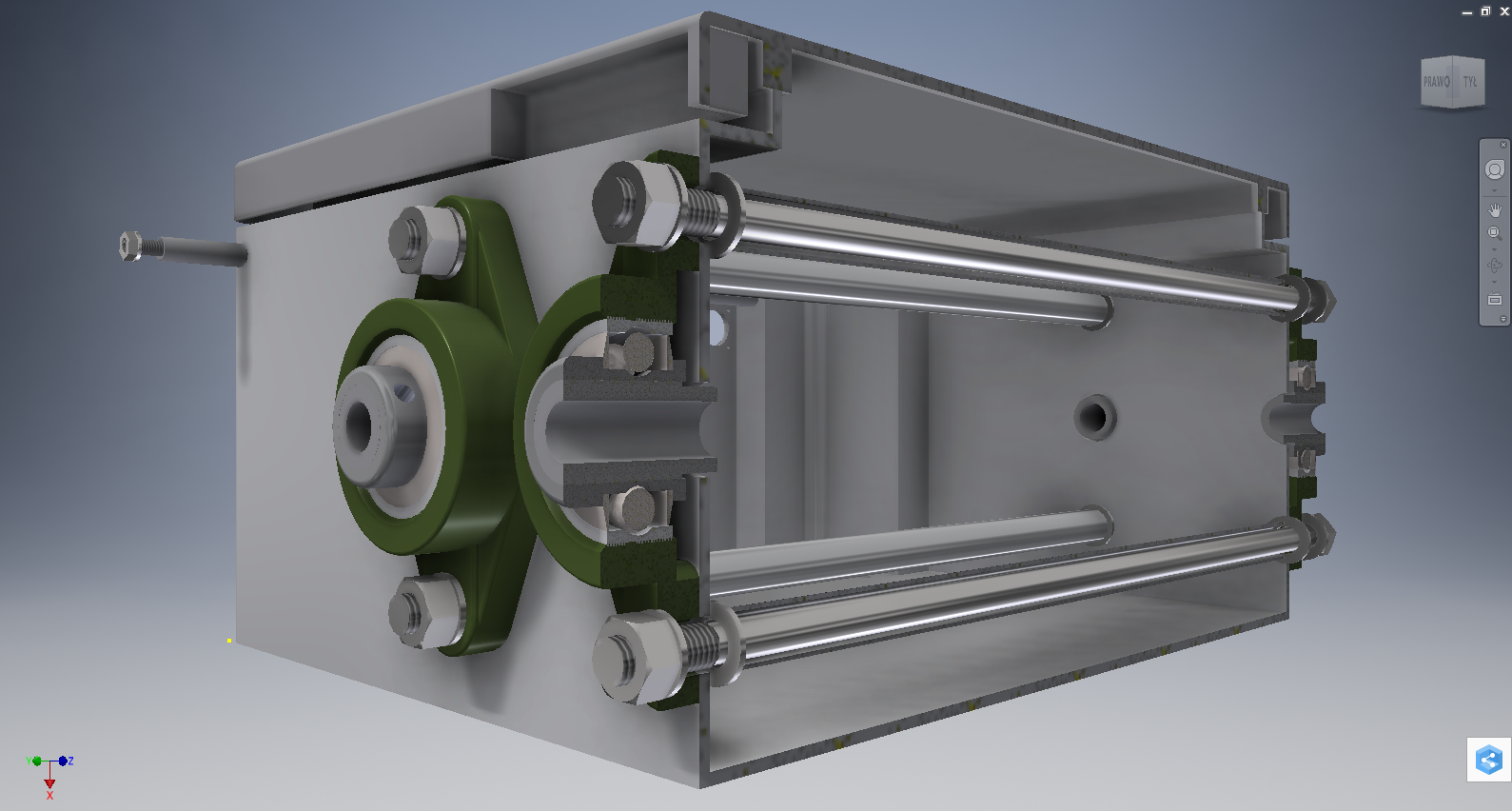
four bearing units are the main components of the rover's suspension
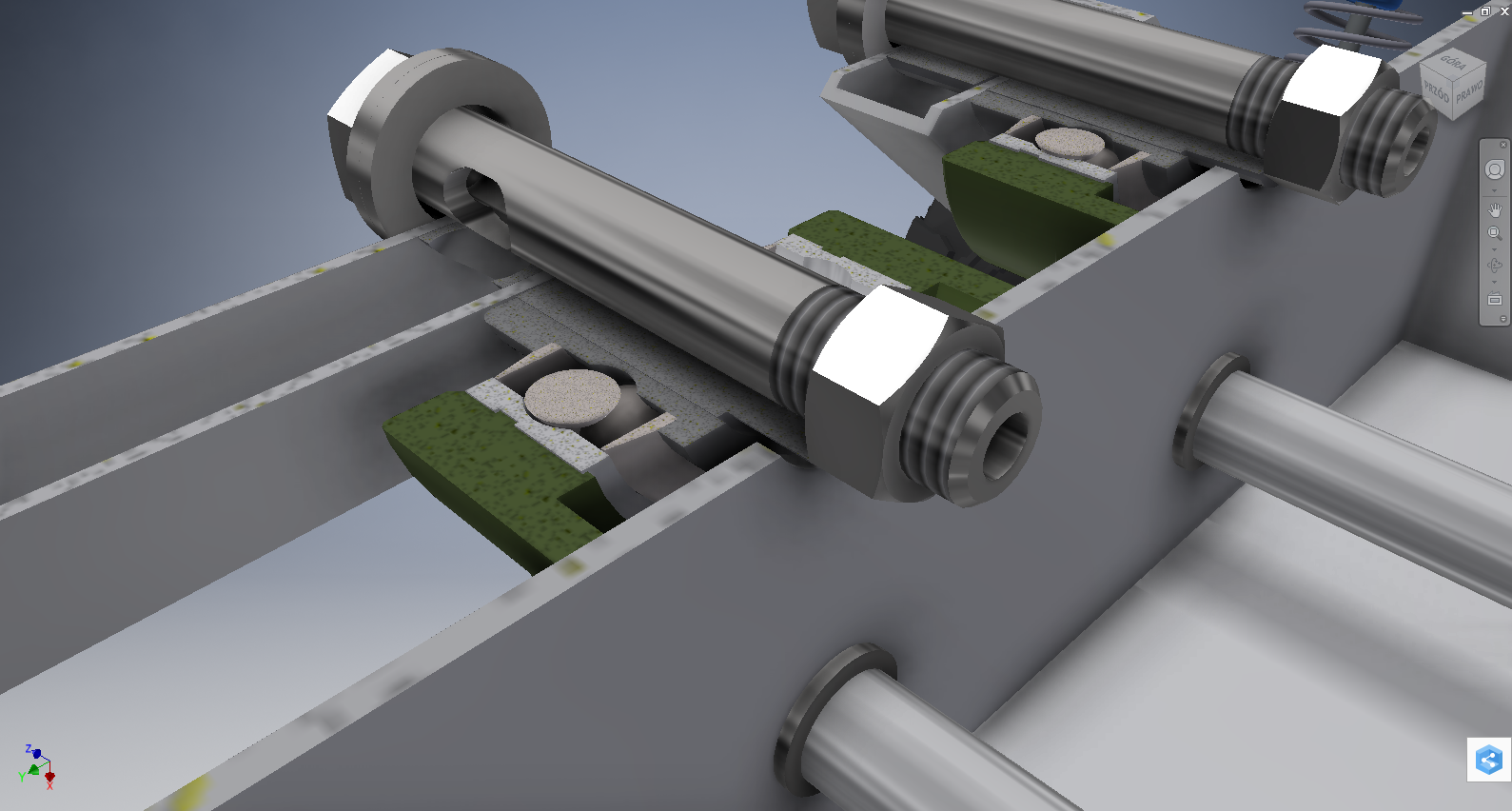
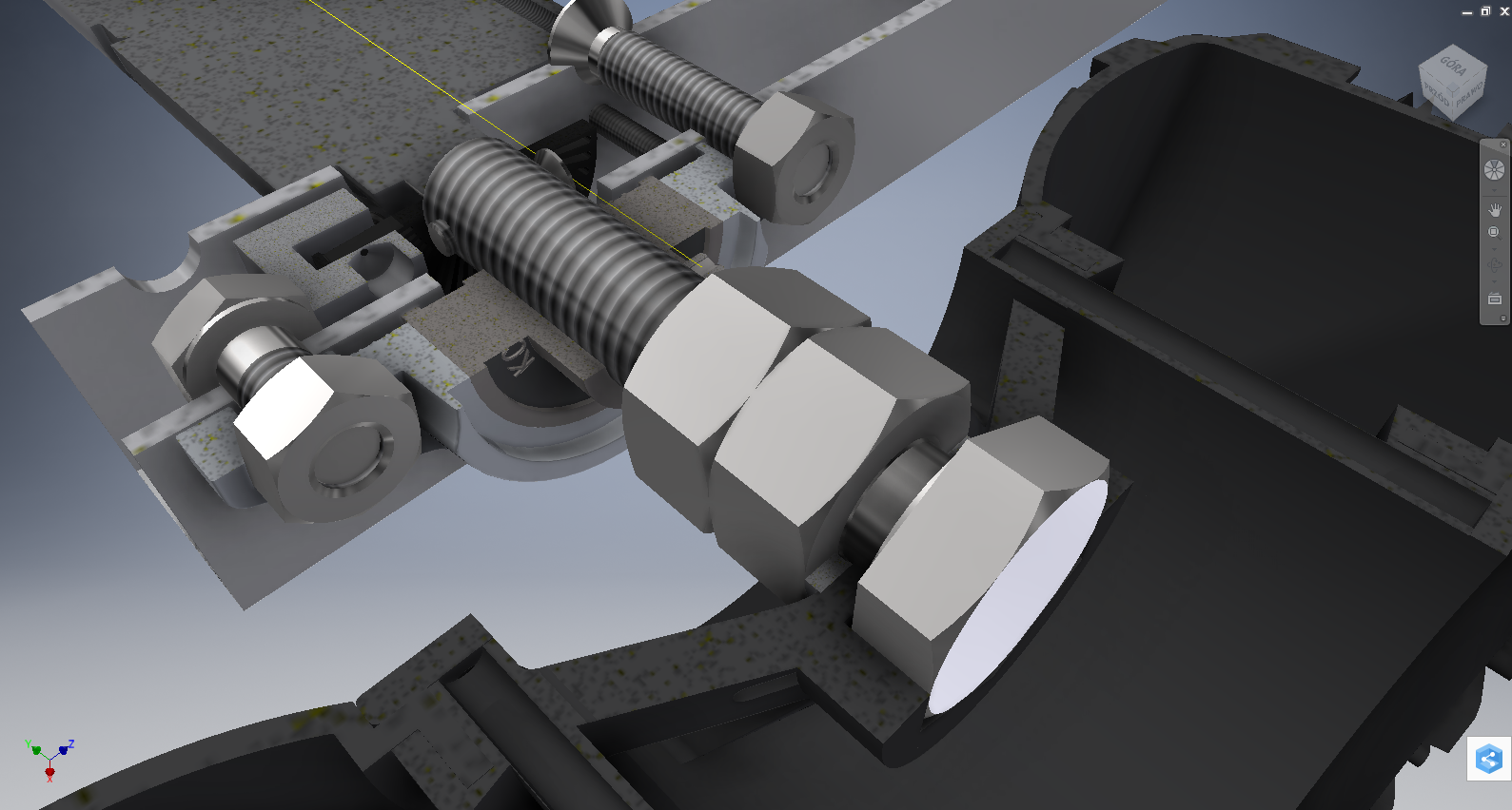
mounting screw of the swingarm with the port for wiring, made by lathe and table drier
routing the wires to the motor

suspension system

scheme of the drive system

drive axle mounted on the drive shaft
the way of mounting wheel on drive axle
Power-supply system
- independent supply for logic and motors
- XL4015 as step down voltage conventer
- three fuses for each battery pack

power-supply system
Electronics
- self-made PCB board, which is an extension board for Raspberry Pi
- Raspberry Pi 3b:
- main unit
- direction control of motors
- communication with workstation via UDP
- communication with Atmega328P via SPI
- communication with PCF8591 via I2C - Atmega328P:
- PWM generator
- speed control
- collect information about the speed from encoders - VNH2SP30
- motor driver - PCF8591
- sending information to the Raspberry Pi about current consumption of motors
- sending information to the Raspberry Pi about batteries voltage level - LM339N
- using as a low level support for encoders

hardware architecture
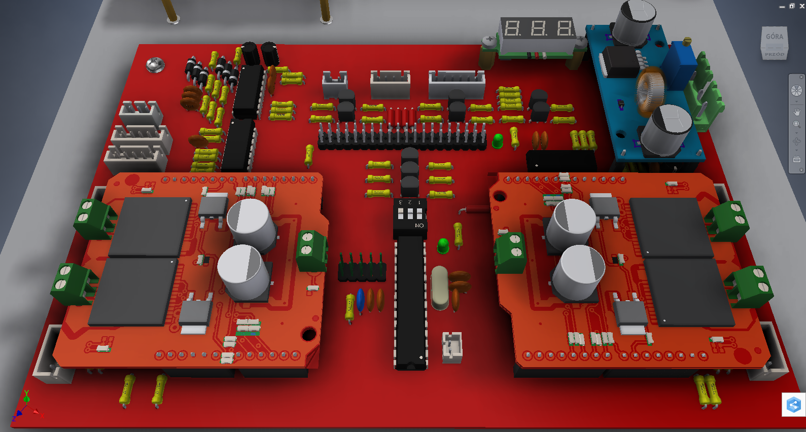
PCB board model
Software
- Atmega328P -- Eclipse IDE for C/C++
- Raspberry Pi 3b (Rasbian) -- Adafruit webIDE, library: Wiring Pi and Qt 5.7.0
- Desktop application (Windows 10) -- Qt Creator 4.1.0, library: Qt 5.7.0

block diagram of the desktop application
Summary and my questions
Work on rover allowed me to expand my knowledge and skills, project is still open. I dropped on github: Inventor and Eagle files and also source code. I will be happy to answer any questions you may have :) if I could ofcourse ;). But first, I have some questions:
- I get strange outcome from encoders output, I know that I have a mistake in Schmitt Trigger module ( forget about feedback), but some encoders seems to work fine and some not, let me show that on the pictures. Maybe someone had the same issue?


- When I was doing the tests, I damaged two motors (gear ratios), therefore I want to replace the motors. I think about wiper motors, so what do you think? Is it good idea?