


micro servo robotic arm arduino based using 10k pot
hello guys....
we have another project micro servo robotic arm..
basically this arm is arduino based on micro servo motor using 10k potentiometer..
this arm used industrially but in this project we are are try to create this robotic arm.
Step 1: Components

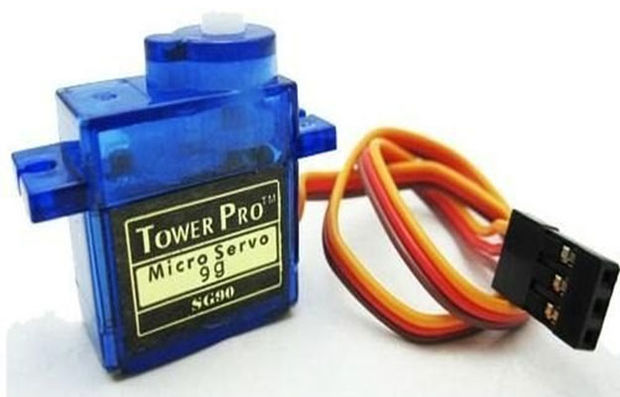
1:-servo motor(4 piece)
2:-arduino uno
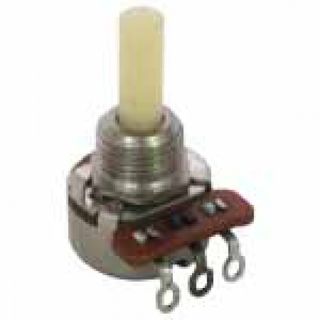
3:-10k potentiometer(4piece)
4:-battery(power bank)
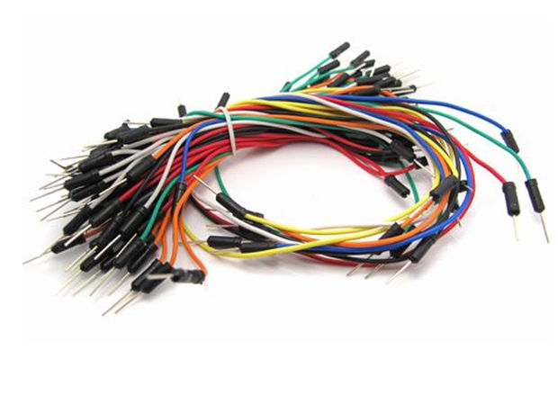
5:-jumper wires
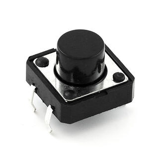
6:-push button switch
Step 2: Potentiometer Connection
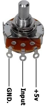
here see this pic......for conection
pot have 3pins...
middle pin is input...which is connect to arduino analog pin
right pin is connect +5v
left pin is connect to gnd
Step 3: Servo Motor Connection
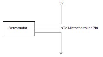
servo motor have 3pins..
one pin is connect to +5v(identify by color red)
another pin is connect to gnd(identify by color black).
next pin is connect to microcontrolller arduino.....(identify by color yellow)......
Step 4: Circuit Diagram
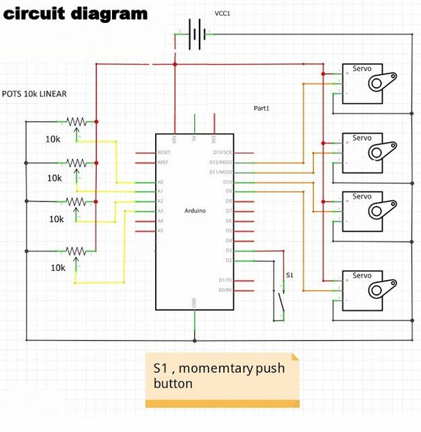
here...
10k potentiometer are connected linearly to the arduino to analog pin a0,a1,a2, and a3.
servo motors are connected to the arduino pin 9,10,11,12...
and s1 is push botton switch thats connected to the 2 and 3 arduino pin.
also,power source is connect to the power bank..
Step 5: Uploading the Code
here is the code...
thats arm controlled by 10k pot and s1 switch is used movement saved...
int PosCount = 0; // to count number of positions increased when button pressed
int PosCountMax = 0; // number of positions recorded when double button push initiates replay mode int PosReached = 0; // used to check that arm has moved from one recorded position to next position void setup() { for(int i = 0; i <100 ; i++ ){ for(int p = 0; p <4 ; p++ ){ ArmPos[i][p] = -1; } } pinMode(PinButton1 , OUTPUT); digitalWrite(PinButton1 ,LOW); pinMode(PinButton2, INPUT_PULLUP); // I have made a small change here due to problem using some Arduinos //attachInterrupt( digitalPinToInterrupt(PinButton2),ButtonPress , LOW ); // digitalPinToInterrupt(PinButton2) may not be defined! attachInterrupt( 1,ButtonPress , LOW ); // interupt to capture button presses // attach servos to relervent pins on arduino nano Arm0Servo.attach(12); // grip 90 to 180 open limits of servo movement Arm1Servo.attach(11); // elbow to 130 up Arm2Servo.attach(10); // shoulder 10 to 50 down Arm3Servo.attach(9); // turn 0 to 180 right }
void loop() { switch(mode){ case 1 : // program robot arm. 1 press to remember position. 2 presses to progress next case 2 replay mode // analogRead(pin) that reads poteniometers on training arm PosArm[0] = map(analogRead(14),480,1024,180,90); // map (480,1024 value from potentiometer to 180,90 value sent to servo) PosArm[1] = map(analogRead(15),180,1000,130,10); PosArm[2] = map(analogRead(16),950,400,80,10); PosArm[3] = map(analogRead(17),0,1024,180,10); MoveArm(); // call method if(buttonPress == 1){ // flag set by interupt when button is pressed buttonPress = 0; // reset flag if( millis() > (lastButtonPressTime + 1000)){ // only one button press in one secound // record position of arm PosArm to array[100][] of armpositions ArmPos[PosCount][0] = PosArm[0]; ArmPos[PosCount][1] = PosArm[1]; ArmPos[PosCount][2] = PosArm[2]; ArmPos[PosCount][3] = PosArm[3]; if( PosCount < 100) { // stop recording if over 100 positions recorded (memory limitations) PosCount++; } }else{ // more than one button press mode = 2; // go to next phase PosCountMax = PosCount; // set number of arm positions recorded PosCount = 0; // reset count ready to read arm position array from begining } lastButtonPressTime = millis(); } break; case 2 : // read arm position array PosReached = 0; for(int i = 0; i <4 ; i++ ){ //adjust servo positions // we move the servos in small steps and the delay(20) makes arm motion smooth and slow if( PosArm[i] > ArmPos[PosCount][i]) PosArm[i] = PosArm[i] - 1; // if actual position is greater than requird position reduce position by 1 if( PosArm[i] < ArmPos[PosCount][i]) PosArm[i] = PosArm[i] + 1; // if actual position is less than required position value increase position valuue by 1 if( PosArm[i] == ArmPos[PosCount][i]) PosReached++; // check if servo has reached required position/angle } if(PosReached == 4) PosCount++; // if all 4 servos have reached position then increase array index (PosCount)to next position in array if(PosCount == PosCountMax) PosCount = 0; // if end of array reached reset index to 0 and repeat. MoveArm(); // physically move arm to updated position, this is broken into small steps delay(20); // pause between moves so over all motion is slowed down break; default : break; } }
void MoveArm() { // write arm position data to servos for (int i = 0 ; i < 4 ; i++) { if (PosArm[i] < 5) PosArm[i] = 5; // limit servo movement to prevent hitting end stops if (PosArm[i] > 175) PosArm[i] = 175; // servo.write limited 5 - 175 } Arm0Servo.write(PosArm[0]); Arm1Servo.write(PosArm[1]); Arm2Servo.write(PosArm[2]); Arm3Servo.write(PosArm[3]); } void ButtonPress(){ // interupt to capture button press if(micros() > (bounceTime + 3000)){ // debounce timer bounceTime = micros(); // ingnore interupts due to button bounce buttonPress = 1; // flag for button pressed } }
just..copy the code..and paste to in arduino programme and then comile..and at last upload to arduino board.
Step 6: Result
how to build this project???...
this video link of our channel s_r tronics on you tube will be helpful to make this project...
so guys...
this is our s_r tronics channel..and subscribe our channel to stay tunned with us..
and plz likes and do comment in inbox..