


MDi-eins
Hello all you guys. It's been some time I'm thinking about of build a kind of interactive robot (something like a butler, service robot). Recently I saw some projects that have inspired me. So, I decided to build my own. Also, some inspiration comes from the classics R2D2, Johhny #5, Wall-E and others.
Interactive I mean, first, interacts with me, but more important: interacts with other robots. How to interact with me I don't know yet what method I'll utilize, but for the interaction with other robots it will utilize a simple method: TSOP1838. It's an IR receiver. I just bought a few. It's simple: the first robot sends an IR signal and the other receive it, interprets, and sends back an answer (another IR signal). It means that they can comunicate together to do some tasks, for example. How it works we will see later. Now look below how goes the work.
P.s.: MDi-eins means: Mech Dickel Interactive #1.
----- List of materials -----
Here I'll put all the materials as the project advances.
- 100mm PVC tube;
- 2mm polystyrene;
- Instant adhesive;
- Sandpaper;
- Epoxy;
- Spray paint.
----- Electronics and Mechanics -----
- Arduino UNO;
- Jumper wires;
- Breadboard;
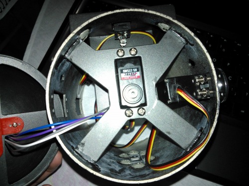
- 2x HS-5245MG;
- 2x HS-225MG;
- 2x HS-82MG;
- M3 screws and nuts;
- HC-SR04;
- 4x Lynxmotion spline metal servo horn;
- Lynxmotion Steel Phillips Pan Head Screws - 3 / 8" x 2-56;
- 4x AA 2500 mA battery;
- ADXL335 accelerometer.
----- May 30, 2013 -----
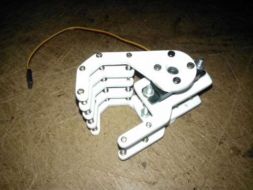
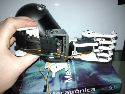
This project is going slower than I would like. First because I was waiting some parts, second because I was a bit confused about how I really want to this little guy looks. But this week I decided that this project should have the function of grab things, and I started the work on his hands.
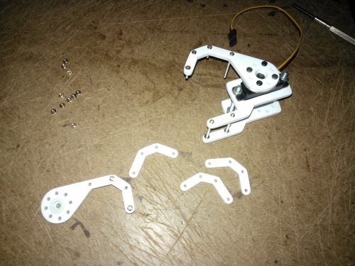
My design is inspired by the Lynxmotion Robot Hand A. The long screws will be changed by nylon standoffs when they arrive.
I'm making also some sketches for the locomotion method, since now I have some DC geared motors and tank treads.
----- February 21, 2013 -----
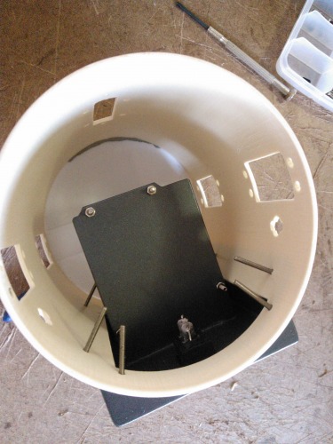
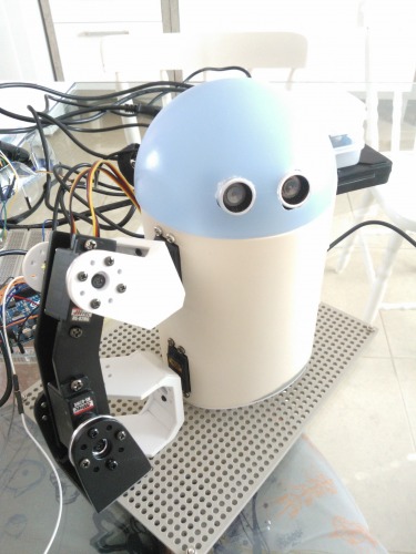
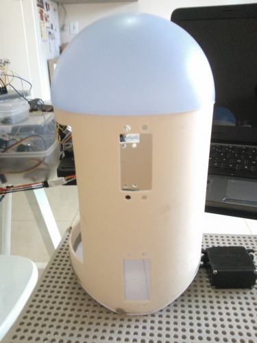
Just a little update. Finished the painting of the body and dome head and the inner brackets (for the head).
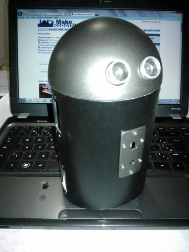
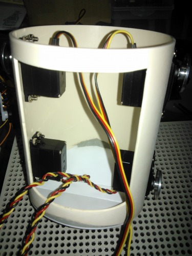
Here you see how it looks inside of the body and head.
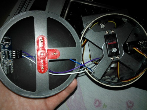
The bracket of the servo to turn the head left and right.
----- February 16, 2013 -----
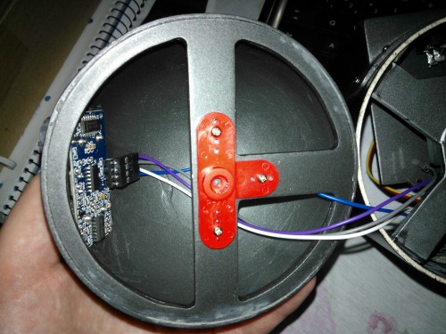
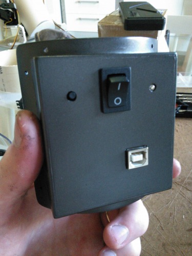
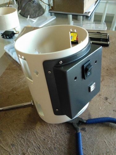
Another day of work. Today this little guy got a "electronics bag".
I've utilized the tonner transfer method to make some pieces.
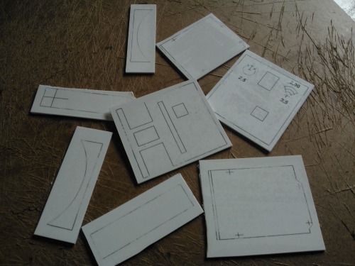
And that pieces turn into a board bracket (the "electronics bag"), that will be placed in the back of the body.
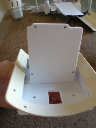
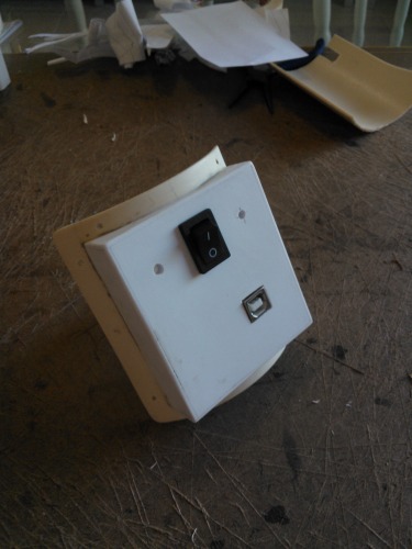
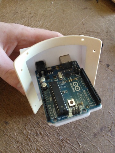
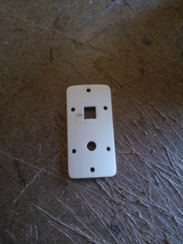
And give it some color... In the left little hole is a push button for reset and in the right hole a power led indicator. As I'll place the batteries inside of the body, the Arduino's P4 jack don't need to go outside the bag.
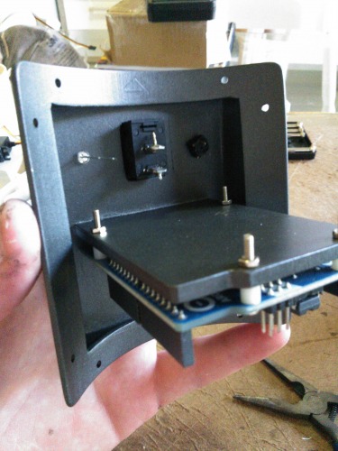
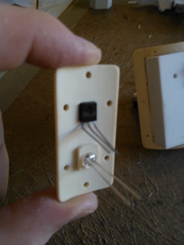
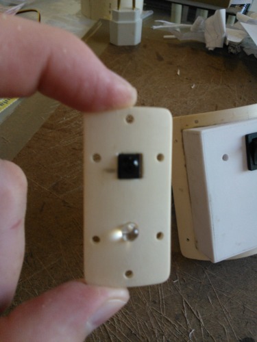
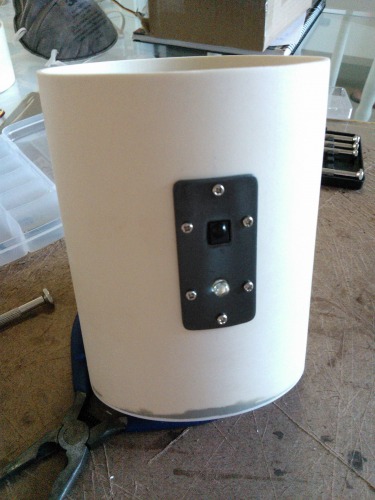
I've worked also on the IR module (receiver and emitter) that will be on the front of the body.
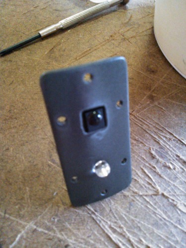
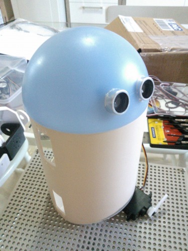
The dome head got a new color too.
That's all for today. Maybe tomorrow I'll paint the body with matte black paint.
----- February 10, 2013 -----
Just added some brackets (originally made for other project) to simulate arms and help with the balance. In the video you see the body inclination with the ADXL335 accelerometer inputs. This allows the robot cross over small obstacles and don't fall backward. The lower brackets are just to hold the body in place.
----- February 9, 2013 -----
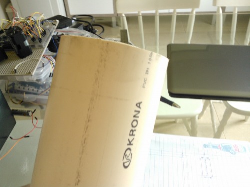
For the body, I utilized a piece of 100mm diameter PVC tube.
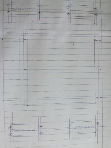
A hand drawing on paper to determine the holes and servo snaps.
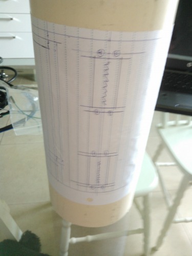
The upper and lower cut I made with hacksaw. The lower cut goes a bit irregular. After I fixed it with epoxy.
To facilitate the "inner cuts" I made few small holes with drill, then I cut it with sharp blade.
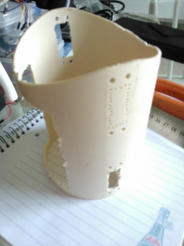
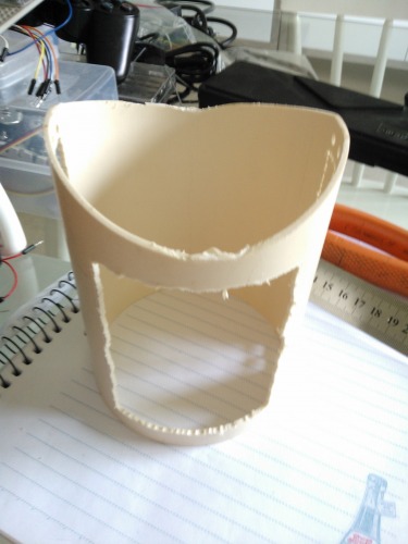
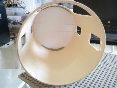
The lower hole of the tube (which in this pic you see in up) was closed with pieces of polystyrene.
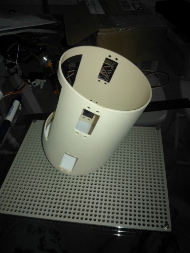
Good space to put all the electronics, batteries and others...
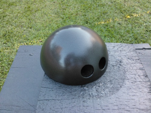
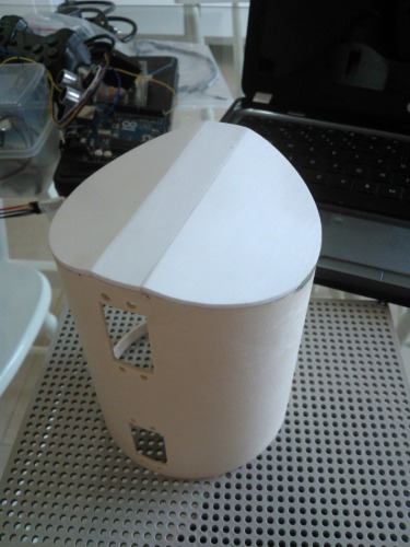
This dome was a kitchen utensil. Hope my wife don't discover it. :)
Attached the servos of the arms and for the body inclination.
I forgot to mention before, but the mobile method will be tank treads (Tamiya). I'm waiting for the DC geared motors that I've ordered.
Will run around autonomously and remote controlled, interacts with other robots (maybe)
- Control method: Autonomous and remote controlled
- CPU: arduino uno