


MBC v1
MBC v1 (Mobile Bot Collector)
Description.
This small bot will collect small objects of different colors. Also will avoid obstacles.
It uses an Arduino Duemilanove with ATMEGA 168 and several personal shields designs for it.
Status:
hardware 90%
software 70%
Working ...
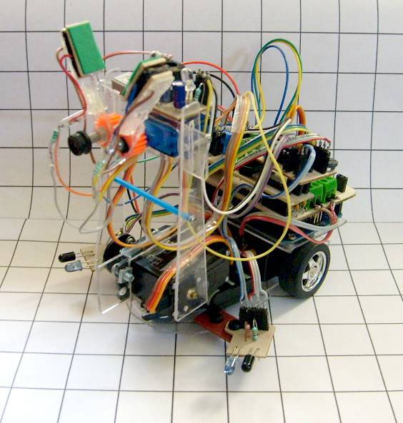
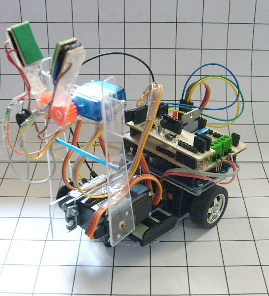
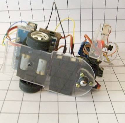
0 WIP Pictures.
1 Circuit Design
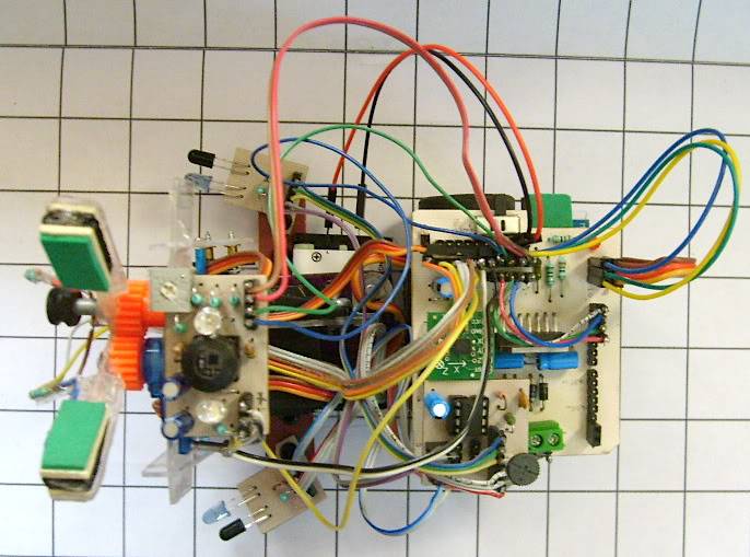
1.1 Motuino v1.2
The Motuino board is used to control two DC motors using the L298 with two pairs of shottcky diodes. Also it contains connectors for the sensor board and it's possible to connect two servo motors.
The Motuino was designed in Eagle, I'm plannig to order pro PCBs from pcbcart.com.
The figure 1.1.1 shows the board designed in one layer, figure 1.1.2 it's the final prototype created by homebrew pcb technic.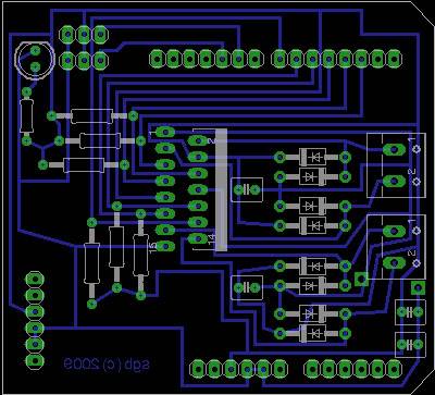
Fig. 1.1.1: Motuino v1.2 Design.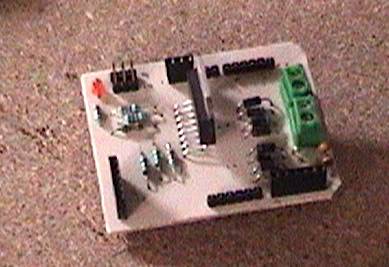
Fig. 1.1.2: Motuino v1.2 PCB.
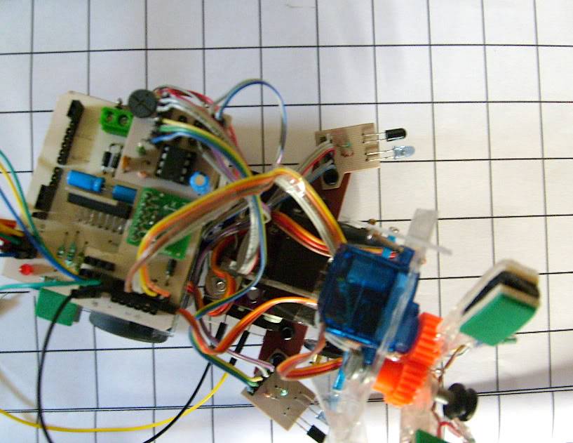
1.2 Sensor Board v1.2
The sensor board (SB) connects all sensors that the robot will use. This sensors are: IR proximity sensor, accelerometer, pressure sensor and color sensor.
In figure 1.2.1 its show the distribution of the connectors. Figure 1.2.2 is the prototype itself.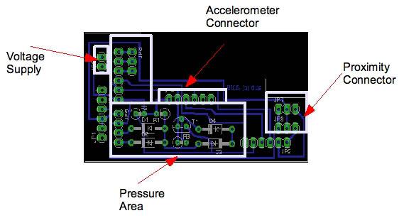
Fig.1.2.1: PCB design and distribution.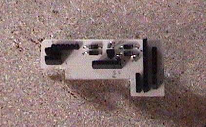
Fig.1.2.2: PCB for SB v1.2.
Voltage Supply - Nominal 5V
Accelerometer - Designed to connect the ADXL320
Pressure Area - Using a NAND, one port its fixed to logical 1, the other connected to the sensor. This sensor it's based in the DIY FSR (http://www.instructables.com/id/DIY-Force-Sensitive-Resistor-FSR/)
1.2.1 Sensor Board 1.3
This board is an updated version, Now includes a tiny switch and voltage regulator for my new battery power supply. Figure 1.2.1.1 shows board distribution, figure 1.2.1.2 it´s the new board.
Update 1: Working on SB 1.3.1....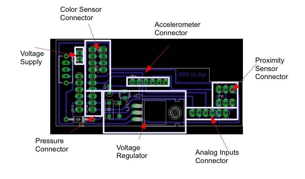
Fig 1.2.1.1: Board distribution for SB v1.3.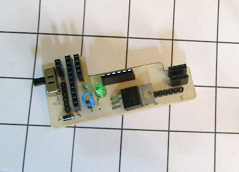
Fig. 1.2.1.2: Board SB v1.3 assembled.
1.3 Pressure Sensors
Based on the nice tutorial for the FSR, I tested and were created two pairs of sensors for the grip. Figure 1.3.1 Shows the parts of the finger. In Figure 1.3.2 both sensors are mounted. This version is used with SB v1.3.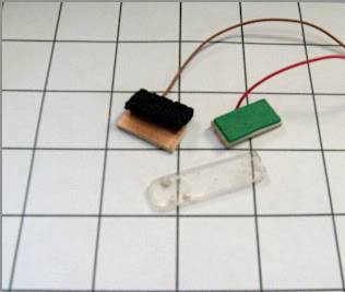
Fig. 1.3.1: Finger for the grip 1 x 2 cm.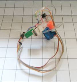
Fig. 1.3.2: Mounting the fingers to the grip.
1.4 Proximity Board
This board uses a 555 timer to send a base frecuency to the IR LED. With this circuit it´s controlled two LEDs, and this signal its used to know when an object it´s close to the bot. Two small boards contains the IR LEDs and phototransistora, They are mounted at both sides of the bot at 40 - 45 degrees each one. In figure 1.4.1 and 1.4.2 its show the PCB design and figure 1.4.3 shows the final board.
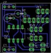
Fig. 1.4.1: PCB design for frecuency and data signals.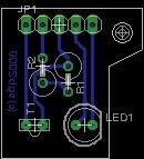
Fig. 1.4.2: PCB design for IR LED and phototransistor.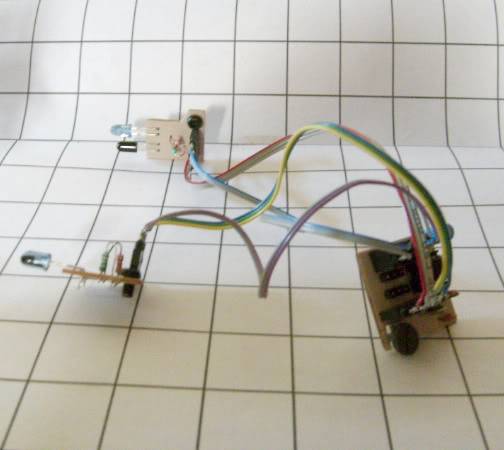
Fig. 1.4.3: Mounting boards for the proximity sensor.
1.5 Color Sensor v1
This board uses an OPT101 as color detector sensor. It contains one high intensity white LED and one RGB LED. Also it will be use as distance sensor to find the object to collect. Figure 1.5.1 shows the PCB design and figure 1.5.2 the assembled board.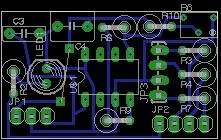
Fig. 1.5.1: Color Sensor PCB design.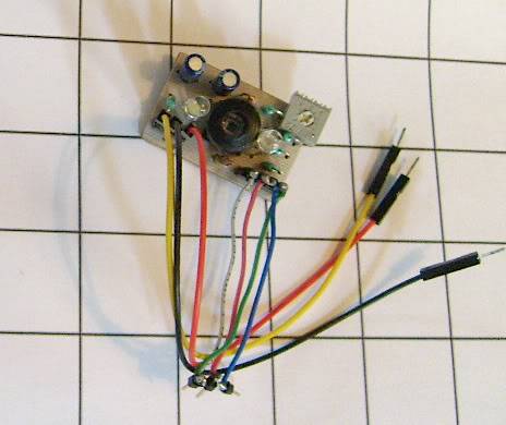
Fig. 1.5.2: Color Sensor assembled.
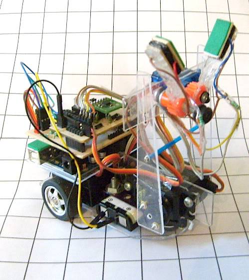
2 Robot Design
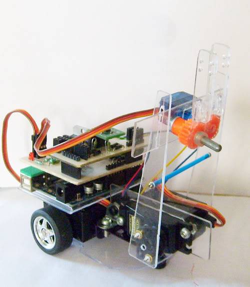
The robot it's a small mobile able to collect small color objects. MBC stands for Mobile Bot Collector. At this moment the robot weights 280 gr, and use a small rechargeable battery located at the bottom of servo 1. In figure 2.1 we can see the parts and design of the MBC.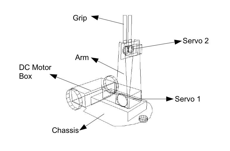
Fig.2.1: MBC v1 design.
2.1 Chassis Design
The mobile base, arm and grip it's made by plastic sheet of 2mm. It's cutted and molded with a cutter and small dremel. In figure 2.1.1 it's show part of the chassis and arm. The DC motor box is part of the chassis and is show in figure 2.1.2.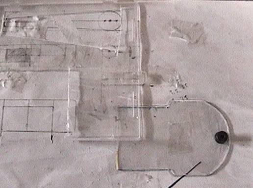
Fig.2.1.1: Plastic parts of the bot.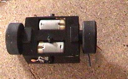
Fig.2.1.2: DC Motor Box.
2.2 Arm Design
The arm uses the hx5010 servo from Hextronik. It's mounted using the piece 518 from Meccano.
Both parts use small screws to join the plastic parts to the base.
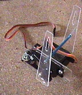
Fig.2.2.1: Arm for the MBC.
2.3 Simple Grip
The grip uses the tg9 microservo from Turnigy. Two small gears 26p 3p from Meccano are assembled at the top of the servo.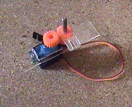
Fig. 2.3.1: Grip construction for the arm.
2.4 Assembling Video
The video shows how all parts are assembled,in this version the grip uses scotch tape to fixed at the arm.
http://www.youtube.com/watch?v=3AjSuzPYkHw
Vid.1: This video shows how all the parts are assembled.
3 Testing Videos
3.1 Testing Motors
The video shows a simple program to control the two DC motors and the two servos.
http://www.youtube.com/watch?v=3DO8BIV2YHM
Vid. 2: Testing MBC motors
3.2 Testing the grip
This video test how the bot will move, at this moment I'm having problems with the battery , now its replace by a 7.2v NiMH AA 2200 mAh.
The grip uses a basic idea in this version. It uses a treshold of 2.5 volts equivalent to 127. The basis algorithm use this value with one cycle to move the grip from 45 to 90 degrees.
int val_act;
int val_ant = 127;
//Arm down
MiServo_B.write(1);
delay(1500);
//close grip and check if there's a change
for (int i = 0; i<= 45; i++){
val_act = analogRead (Sen_T);
val_act = map(val_act,0,1024,0,255);
temp = 45 + i;
MiServo_M.write(temp);
delay(110);
if ( (val_act <= (val_ant + 5)) && (val_act >= (val_ant - 5)) ){
delay(3000); //wait 3 seg
break;
}
}
MiServo_B.write(100);
delay (1500);
Code 1: Basic Algorithm to sense presence of an object.
http://www.youtube.com/watch?v=1TQGUMr1rsQ
Vid. 3: Testing Movements and Grip
3.3 Testing Task 1
Soon ...
avoid obstacles, collect small color objects
- CPU: Arduino Duemilanove
- Power source: 4.5 Ni Nh
- Target environment: indoor