


Maze Solving Robot V3
Yeah I know what you are thinking, "V3? What is this a CNC machine?"
Well no, I really want to get this idea working. I had 2 other versions before this one, but only showed the world the second version. The second was able to do left hand on the wall okay, but not perfect, and i could not get it to go back and drive the shortest path. My design had failed me.
This one will work though. So I present to you V3...
After a few days of working on the design in AutoCAD, I ended up with this one.
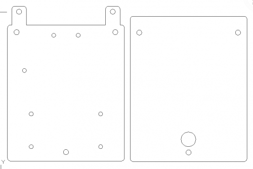
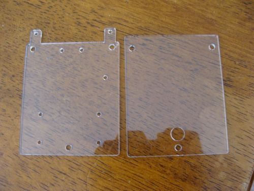
I then brought my design to school where we have a brand new laser cutter. This was the first thing ever cut on it. I wanted to get video for you guys of the laser cutting action, but we ended up cutting it out early than expected because the setup was so easy.
The motors are the ones from my old maze robot. They are available at Pololu
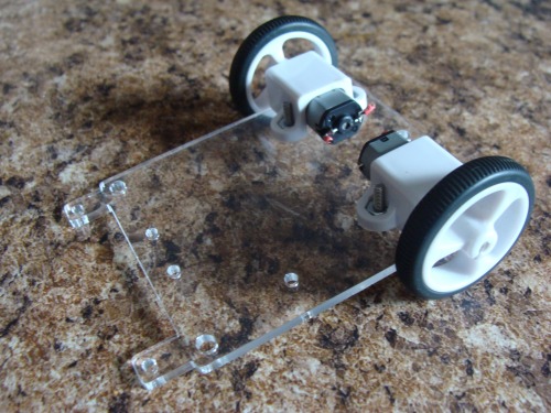
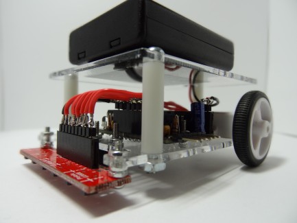
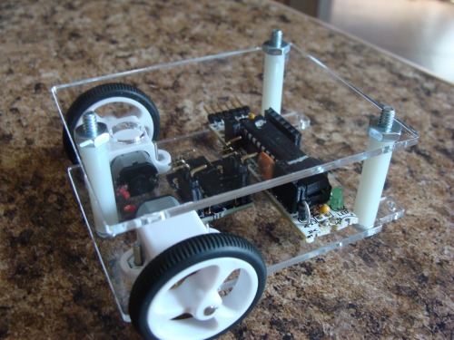
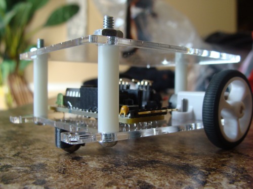
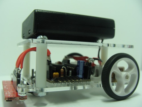
The top deck gets bolted on with 1" spacers. This deck will hold the battery pack which is to be decided.
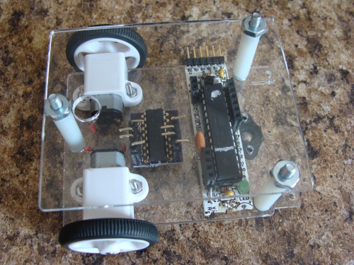
The electronics part of it consists of a RBBB Arduino, My own L293D breakout board, and an array of reflectance sensors (not seen below)
I still need more bolts so i can attach the ball caster and the RBBB
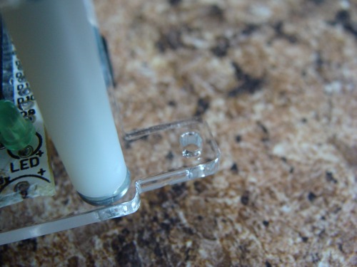
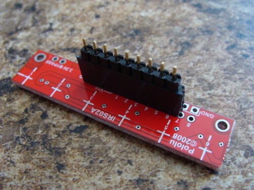
I will be using this sensor array, which will be bolts onto the tabs in the front of the robot. I can adjust the height of it will little spacers.
Well that is it for now.
Update 4.6.11
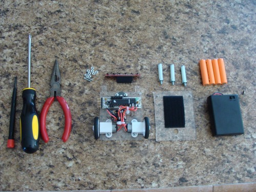
Here are basically all the parts that go into it
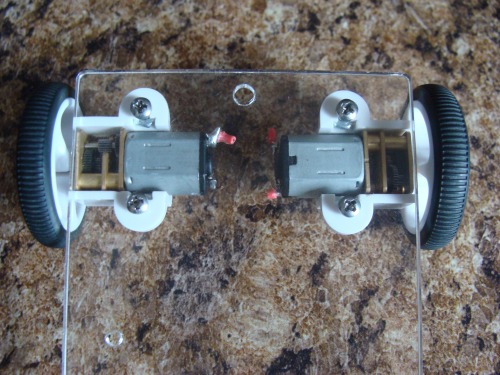
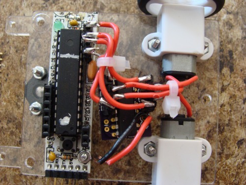
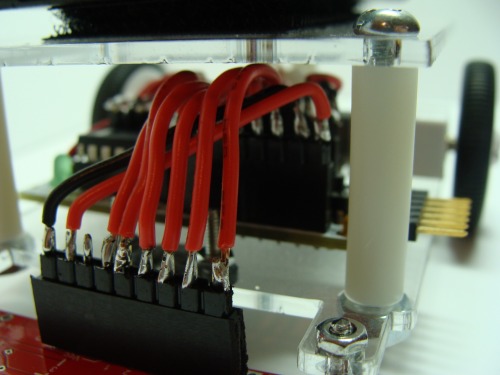
As you can see I have wired up the motors to the motor controller and the motor controller to the Arduino. I actually have another RBBB Arduino board on the way becuase this one does not competely work due to some of my desoldering mishaps.
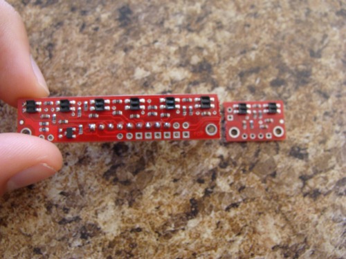
Here is the reflectance sensor from Pololu. It comes with 8 sensors, but 2 of them on the end can be removed to make it a 6 sensor array instead.
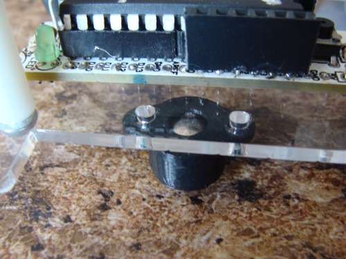
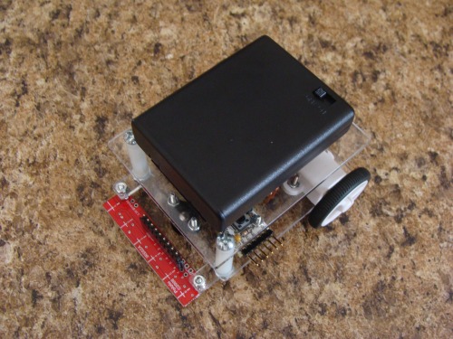
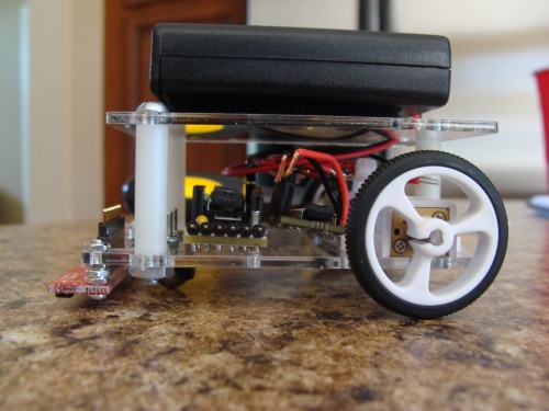
The ball caster and RBBB are now bolted in place.
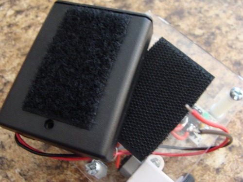
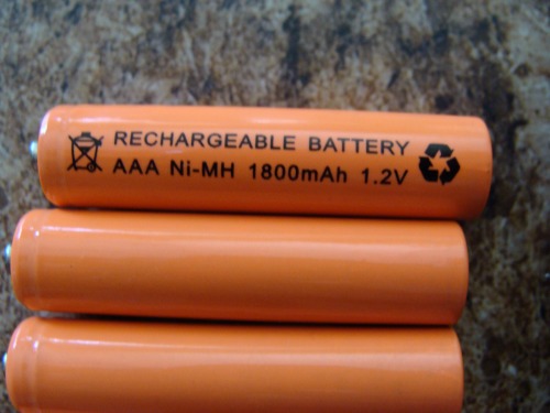
The robot runs on 4 AAA 1.2V 1800mAH batteries (real cheap on eBay). The battery holder gets velcroed on the top of the robot. This battery holder has a built in on and off switch.
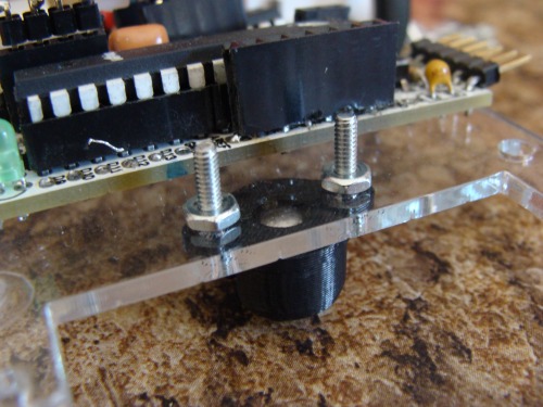
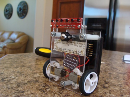
Finally the sensor is bolted onto the fron of the robot. I first add 3 nuts as spacers for the sensor.
Then the sensor is bolted onto the tabs in the front with another nut.
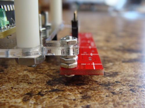
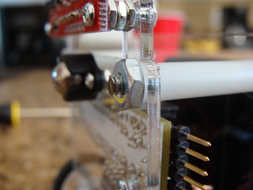
Here is a lock at the clearance. Optimal range on this sensor is 3mm.
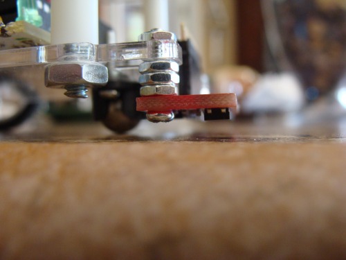
The last thing I have done is cut the 3 long bolts that hold the 2 plates together so they are not touching the ground.
When my new RBBB arrives then I can finish wiring the robot and program the little fellow. Till then here are some more photos:
Update 4.16.11
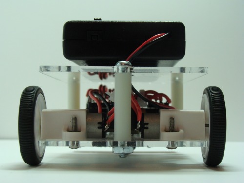
I have had it all wired up and running for a while now. Here are some pictures of that:
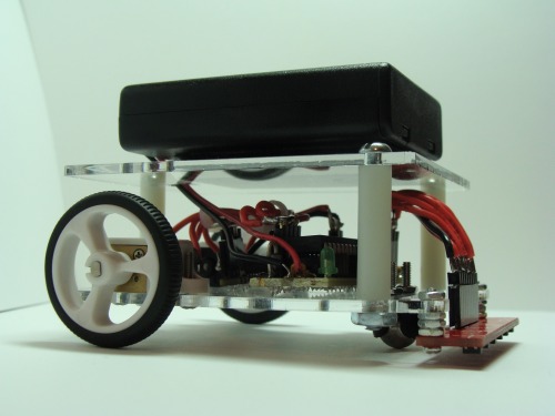
My biggest accomplishment however is finishing the code. It works!
As you know, the robot uses the left hand on the wall algorithm to navigate its way through the maze. It then shortens the path by removing certain combinations of turns it knows to look for and replacing them with fewer turns. For instance, left turn - turn around - left turn = straight.
There are a multitude of things that make this robot hard to program. For instance it has no encoders, and its sensors are in a line meaning that some of the intersections look the same or they look like the finish line.
To make up for not having encoders, the robot is programmed to depend a lot on its line sensors. Its turning functions pay close attention to the sensors in order to stay aligned with the line.
In the video you will see that it speeds up and drives past each intersection. It does this to figure out what is after the intersection which will influence its turns. This also helps it when turning, because it needs to drive a bit forward before turning so it ends up in line with the maze. It also has to make sure it is lined up at each intersection in order to make a proper decision.
Update 4.18.11
I hate doing these updates that are only spaced a few days apart, but this little guy is too much fun.
I have attached the code for the robot. Not really any comments in it.
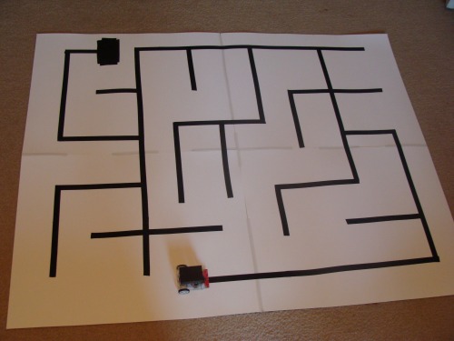
Finally I have made a big maze and uploaded a video of the robot solving it. The robot is looking flawless.
Here is that big maze. The ending of the maze (the black rectangle) is moveable:
Update 7.25.11
"If it ain't broke, don't fix it." I think many of us roboteers do not live by that, including me.
I have changed the robot again in order to make a cleaner and simpler design. This change is based around me wanting to integrate the two seperate boards I had on the previous design into one. I was using a RBBB Arduino and my own motor driver breakout board. That worked, but was not as clean as I wanted it to be.
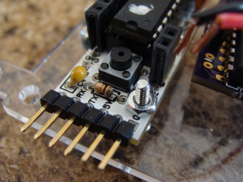
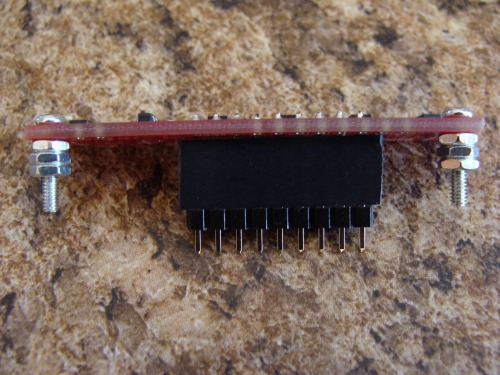
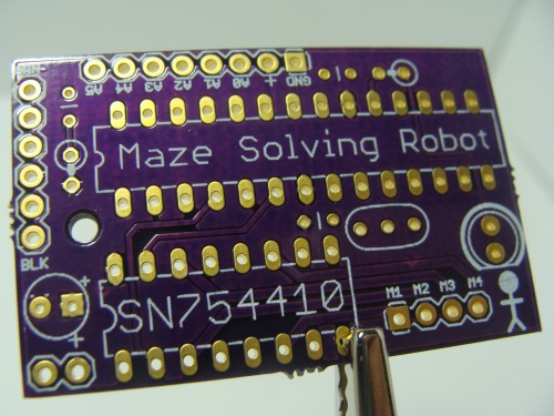
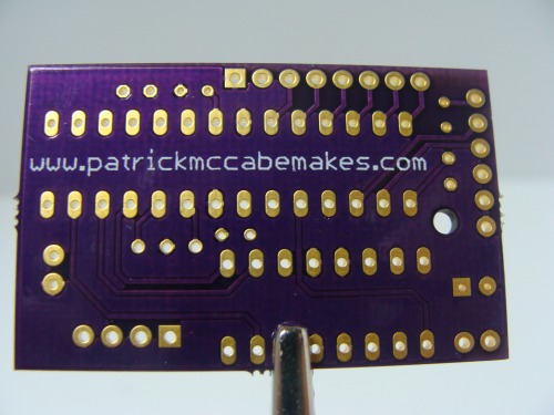
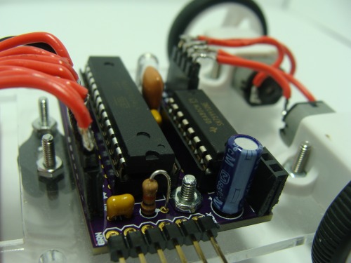
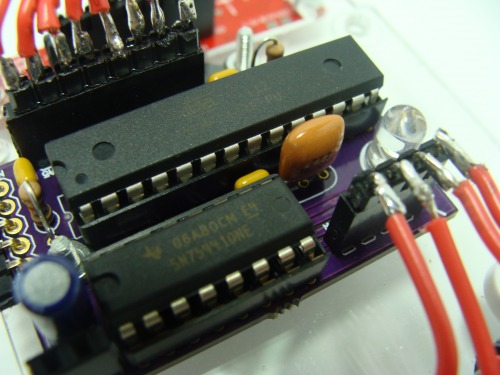
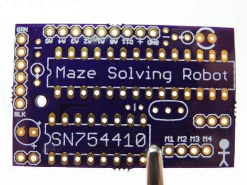
So I designed a new PCB. This one is basically an Arduino with a built on motor driver (SN754410). It has only the pins I need broken out so that it can interface with the sensor array and the motors. Another advantage I added to this board was access to the enable pins on the motor driver which I did not previously have. These enable pins are connected to PWM pins on the Arduino so the speed can be controlled. There is also a LED on pin 13 for debugging.
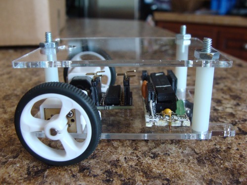
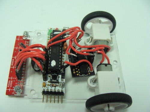
This is what it looked like before the new board:
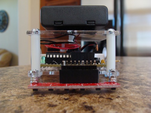
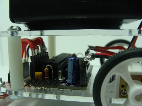
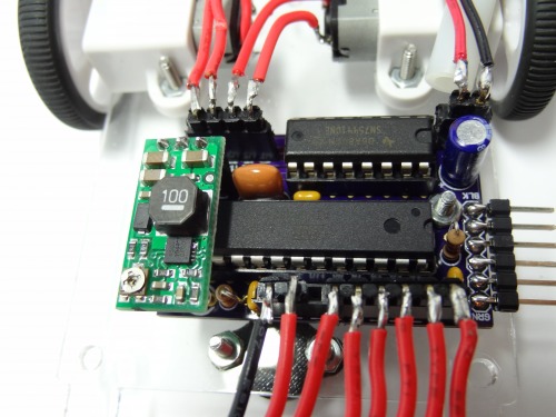
Here is what it looks like with the new board:
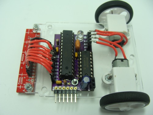
I am very pleased with the new upgrade. I finally feel like I have a stream line design here that could be easily replicated.
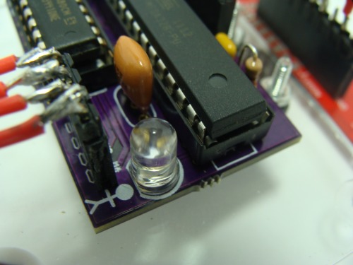
Along with a new board, there is also new code. First off I made it drive faster. The robot is programmed to use the LED to show what it is currently doing. The LED is solid when driving, blinks one sequence when done solving the maze, and another when done driving the shortest path. The robot is also programmed so that it knows when it is placed down after solving the maze and it will then run the shortest path. This way you can take your time placing the robot back down at the starting position where as before it was a timed thing. You can see this in the new video when the LED goes from blinking to solid after the robot is placed down.
Well that is all for now. I still need to make use of the PWM abilities I have for the enable lines. Right now I am not PWMing them. I am just running my old technique of small delays on the direction pins of the motor driver. The new code is uploaded.
Update 08.21.11
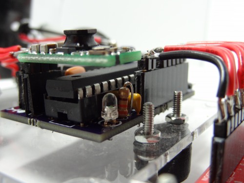
Well I changed the PCB again. I am calling this the final change on this robot. There are a few changes on the PCB. The biggest change is I added a 3 pin header for Pololu's boost regulator. This is the same power setup found on their 3pi robot, but I went with the 2.5-9.5v one. I am using it to supply a constant 6v to the motor driver and motors. This constant supply allows me to tweak the program until it is perfect and not have to worry about the robot slowing down due to battery drain. To accomodate for adding the regulator to the board (I did not want to change the PCB size) I moved the LED to the front of the board and used a 3mm one instead of 5mm. Another change I added was I broke out a digital pin next to the analog pins that allows the IR LEDs in the Pololu reflectance sensor array to be controlled. This is possible because the reflectance sensor array has a built on transistor. This could be used to turn them off when not needed and save power.
There is a new video at the top you can watch. It uses my new code I wrote which makes it faster.
Solves line mazes
- Control method: autonomous
- CPU: Custom Arduino Board
- Sensors / input devices: Reflectance sensor array