


Mapping Rover -- The classic Rover 5 with improved 3D printed axis adaptors
Hi everyone,
this is my first robot project not only on LMR but at all. In November I decided to build the apparently classic Dagu Rover 5 with the awesome offroad wheels. I wanted to start with a "simple" remote-controlled vehicle before making it autonomous. This should be a robot, after all.
The Hardware
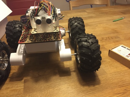
I'm using the Dagu Rover 5 with 4 encoders, the Dagu Rover Motor Controller, an Arduino Mega, a Readbearlab BLE Shield to send the sensor data, 3 SR04 sonar sensors and a Pololu MinIMU 9 compass, gyro and magnetometer. The IMU (and the sonars) are mounted on 3D printed parts. As many people have noticed before me, the axis adaptors for the Pololu offroad wheels are very long. The Dagu Rover chassis isn't very stable to begin with but with the wheels mounted at several cm distance, I was afraid the axes would break at any moment:
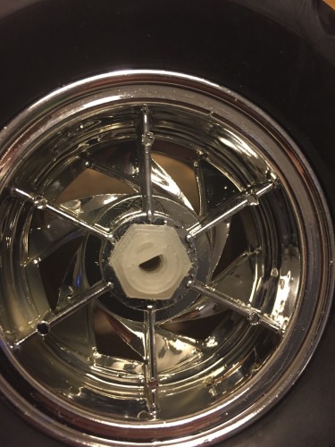
With my new Printrbot Simple Metal, I designed new adaptors that have a 12 mm hex shaft at one end and a 4 mm half circle on the other end:
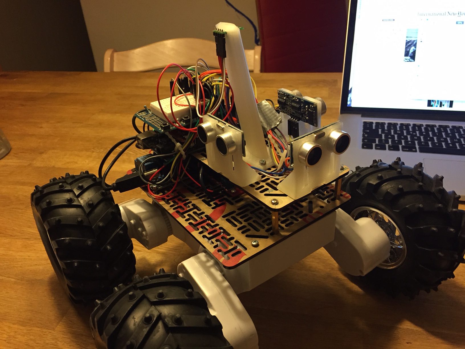
The process took a bit of trial and error but I like the result. I also like the holder for the gyro unit which creates a bit of distance between the magnetic fields created by the motors and the magnetometer:
Both models and all code are available on Github at https://github.com/stheophil/MappingRover
The Software
I'm a Computer Scientist by training. Computers are simple machines that do as they are told. Robots however have to interact with the pesky real world and nothing really works the way it should.
Robots don't drive straight when you tell them to: I'm using the ArduinoPID library to control all four motors so that the wheels turn at the desired speed. I've made extensive tests to tune the PID parameters (see my Excel sheet). The four motors on my Rover behave very differently. To drive at the same speed, the weakest motor needs a 20% higher PWM signal than the strongest motor. The difference is even larger when turning on the spot and some wheels must turn backwards.
A compass is a fickle instrument: Ok, now the rover is driving straight. But in which direction? I tried to mount the magnetometer at a little distance from the motors. I've calibrated the compass using the simple min/max method while the motors are running. I wanted to calibrate them in a real-world situation. That has worked ok. So far, I've avoided calibrating my compass by ellipsoid fitting.
I'm using Pololu's MinIMU AHRS (ported to straight C -- I'm using the awesome inotool.org build system for Arduino) to calculate the Rovers heading.
The robot sends its heading, the distance recorded by the wheel encoders and the sonar measurement via Bluetooth (BLE to be precise which is just barely fast enough!) to my Mac. My central command application is not only the remote control but is also supposed to become the robot's brain. It currently draws the robot's path and builds a map of the robot's surroundings based on the sonar measurements.
Cheap sonars are garbage-in garbage out sensors: What what can you expect for a few bucks?
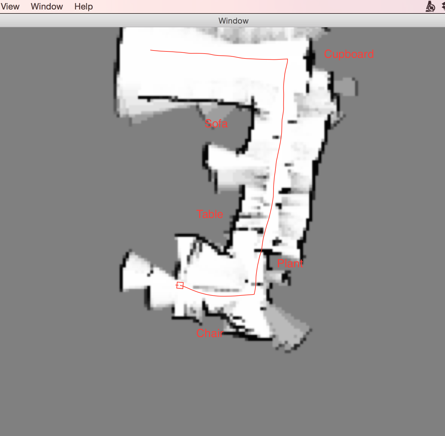
With the ambiguous results you get from sonars with a 15° opening angle, you can only build pretty rough probablistic maps. I'm building an occupancy grid map representation, i.e., a map of the probabilities that a point is occupied. Here you see a partial map of my living room. The darker the color the higher the assumed probability:
The sonar measurements become more precise as the rover approaches the obstacle. If the front sonar sensor were movable, the rover could sweep the space in front of him and remove some of the measurement noise in the map.
Possible Improvements:
At the very least, the Mac command center should control the robot to create some simple maps. Then, it's a robot!
Of course, I have grand ideas for the Rover v2. I've been eyeing the new Raspberry Pi 2 to make the robot truly independent. The Raspberry Pi could use the camera to correct the magnetometer disturbances. The new Lidar Lite laser scanner is looking sweet too.
Update (7 Oct 2015): Making Maps Autonomously
Like I've said above, I already had my eyes on better hardware from the beginning! But first, this robot had to become an actual robot and not a remote-controlled toy. I've just pushed the first (kind of) working version of my autonomous map-making robot to my Github repository. This is how it works:
As described above, the robot uses the very imprecise sonar sensors to create a probabilistic map of its environment. That means the map is a greyscale image were the darkness of the pixel corresponds to the robot's confidence that an obstacle is at that position:
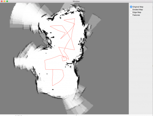
When one of the sonar sensors sends a signal that it detects an obstacle in 2m distance, I update all pixels inside this arc. All pixels with a distance of < 2m are a little bit more likely to be free, all pixels on the arc at 2m distance (+- some tolerance) are a little bit likelier to be occupied. Over time, these probabilities accumulate and give a surprisingly good map if you know how my living room looks. The red line in the picture is the path the robot has taken, the little red square at the center is the robot itself.
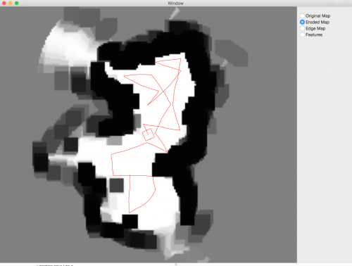
This occupancy map is not very good for navigating. Its resolution is 5cm per pixel, my robot is about 30cm each side. That means the robot occupies a lot of pixels. The robot has to find paths through the map such that it doesn't collide with a black (or dark grey) pixel. This would be much easier if I could have a map where the pixel at position (x,y) is white if (and only if) the robot could be centered at position (x,y) without colliding with a black pixel in the surrounding of (x, y). I can create such a map using an image transformation called an erosion. Eroding the image means that I enlarge all black pixels by the size of my robot. This is the result:
Now, all that is missing is a simple strategy. A random walk would work already, that's what the Roombas did until the very latest model. But I can do a little bit better maybe. An important observation I made when I remote-controlled the robot is that the sonar sensors are very imprecise. They have an opening angle of 15 deg which means that from afar, they don't measure very accurately how wide an obstacle actually is. That means that with a sonar sensor it's better to drive past obstacles at close distance. That is all the strategy I've implemented:
- Make a 360 degree turn to read the environment
- Find the optimum angle which leads past the most obstacles at relatively close range. Closer obstacles are preferred because the further away the target, the less confident the robot can be that he'll reach it on the planned path. The robots IMU is not very precise either so he'll frequently think he's making a little turn, just because there's a steel beam beneath my floor.
- Drive at the optimum angle until the robot reaches an (unforeseen) obstacle or until he has driven past the target.
- Repeat
In order to find the optimal angle in step 2) the robot has to know where he has been. Again, I store this information in a map. I draw a very thick line along the path the robot has already taken. All obstacles along this path are not considered again. This is how this looks:
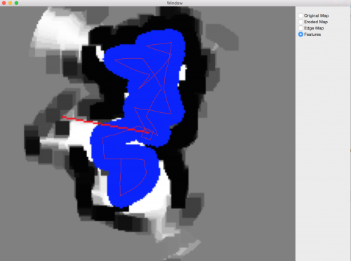
The thicker red line is the path the robot is currently planning to take.
Conclusion
The robot has only an Arduino Mega onboard, not enough to implement any kind of interesting robotics algorithm. I decided early on to develop the algorithms on my Mac instead of putting a Raspberry or similar on the robot itself.
- Programming and especially debugging was much easier this way, having a simple UI to visualize the robot's maps and decision making was very helpful.
- I underestimated the impact the delayed communication over Bluetooth would have. The robot was unable to turn to a specific angle until I reduced the robot's speed significantly. It still overshoots somewhat.
- I started writing some of the algorithms in Swift (like the UI) because I wanted to try it out. This was quite a waste of time for several reasons:
- I'm a C++ programmer by day, so I'm much more productive with that in the limited time I have. Plus, if the upgraded rover should have an onboard Raspberry I would have had to port everything to C++ anyway.
- I noticed only in the last few weeks that I needed a lot of image processing algorithms in order to make the robot autonomous. Calculating the eroded map, calculating distances from obstacles (= black pixels), drawing thick lines over the visited path etc. While Mac OS X comes with quite a few good image processing libraries, again these would not work on a Raspberry. Instead, I've used the OpenCV image processing libraries which most people use for face recognition etc. I had had no idea that OpenCV is much more than just a "Computer Vision" library. It implements a large set of image processing algorithms too.
Update (9 Oct 2015): Now with a video!
There's one to-do item remaining: The map making uses a simple local optimization strategy. At the robot's current position, it chooses the angle that leads the robots past the biggest number of unvisited obstacle pixels. It does not know how to go to unexplored parts of the map if no such pixels exist in the robot's immediate surroundings.
Builds a probabilistic occupancy map from sonar sensors
- Control method: autonomous
- Sensors / input devices: Ultrasound sensor
- Target environment: indoor