


MAEP (Mobile Arduino Experimental Platform)
Hello!!!! This is my first microcontroller robot (besides the Boe-Bot). I decided to learn to use the Arduino because it didn't seem to hard to learn, had a lot of capabilities, and is very popular with many tutorials and examples on the internet, which is very important when you're learning.
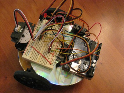
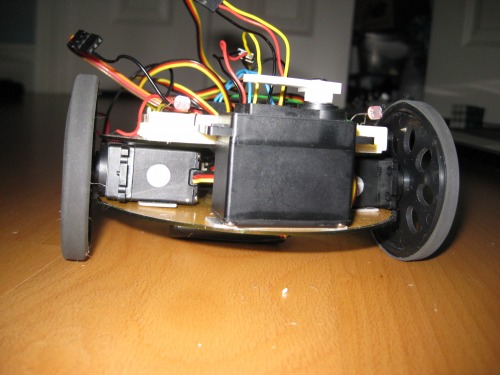
Being just a kid, I don't really have access to power tools for machining parts (well, I could ask my dad to let me use his stuff, but I want to be independent :). Thus, I chose to use blank CD's for the chassis and double-sided tape to stick everything together. It worked pretty well, I must say :).
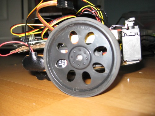
Powering the motors is two HS-311 servos modified for continuous rotation. I cheated a bit with a wheels, because I used the Boe-Bot wheels which are not designed for these types of servos. However, I just screwed them in tight, and the servo shaft slipping inside the wheel was no problem.
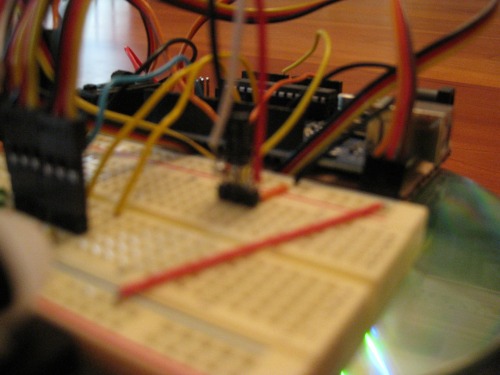
Since I wanted to use this robot to learn Arduino, I got a breadboard instead of permanantly soldering circuits in place. Instead of getting the protoshield for I chose a seperate breadboard because A) It's cheaper and B)It has more space. Before I got a new breadboard I had a huge one that had to be stacked up on a deck of cards to fit. It's shown in my first video below.
For power, I have two batteries. One 4.8V Ni-Cad battery is used to power the servo motors, and one 9V alkaline battery is used to power the Arduino. I don't have a 9V clip with a barrel jack on the end, so I'm kind of "cheating" again by plugging in the 9V battery into the Vin pin on the Arduino.
Originally, I had no sensors on the robot, but I now have photoresistors and have programmed it to be phototropic, which also gives it some obstacle avoidance abiltiy, but not that great. I plan on adding a Sharp Infrared sensor like what's on the "Start Here" robot (I'll bet you were wondering what that third servo is for :).
Update 5/15/2011
I have placed an order from Pololu for a Sharp IR sensor and cable, switch for the NiCad battery, and double-sided male headers. Speaking of a switch for the NiCad battery, I have a funny incident to recall. The other day I was holding the robot when I saw smoke rising from it. In alarm, I put it down and realized the NiCad battery was short-circuiting against the negative lead of the photoresistors. I pulled the burning-hot wires out of the battery header and saw that the red wire was charred and some of the insulation was burned off :) So THAT is why they always say not to short circuit batteries!
Update 5/22/2011
My parts arrived several days ago, and I have added the Sharp IR sensor to the robot. I decided to use the circular servo horn rather than the arm. I used double-sided tape to attach the Sharp IR on to the servo, just like I did for everything else on the robot.
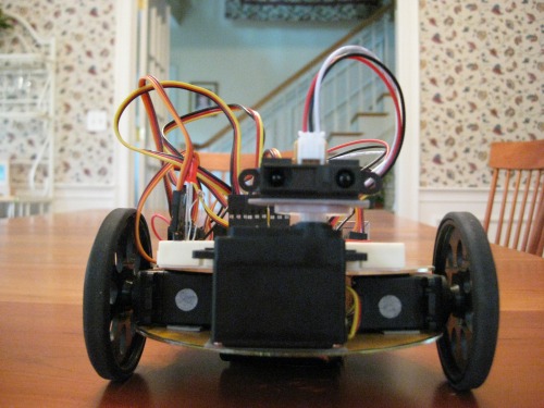
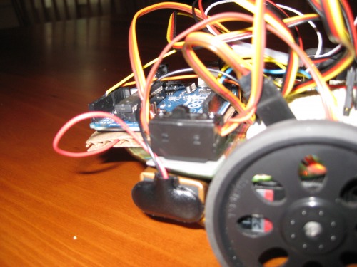
In order to plug it into the breadboard, I soldered the leads to a male header. I also soldered in a 10 uF capacitor between VCC and GND as the manufacturer recommends. It's a little blurry, but here is a picture:
I also got a proper power switch for the NiCad, although I still plug the main 9V battery directly into Vin on the Arduino. I also added an LED to indicate whether or not the motors power is on. The LED is just hooked up to the power rail for the NiCad battery with a 1K resistor in series. I'm thinking about having the microcontroller sense whether or not motor power is on and not running the program until the motors are on. On top of all that, I got double-sided male headers which I plug the servos and battery into. This really cleaned up the wiring.
I'll post a video as soon as possible! I also included the Arduino code. Feel free to use it for your own robots!
Update 7/8/2011
Wow, I kinda broke my promise to post a video ASAP.... well, late is better than never! You'll notice in the video I also added a PNP transistor to reset the robot when the motor power is turned on. The base is attached to the motor battery, and it ties the RESET pin to GND so that when the motor power is off, it is as if their is a finger on the reset button. That way, the robot runs through all of the startup code even if the motors are turned on after the electronics.
In my list of goals, I added RC capability and adding an LCD screen for debugging as possible additions. I don't know where I will put the LCD on the limited space of MAEP. I have a reciever and transmitter, so I'll look into how I might make an RC mode.
Update 1/29/2012
I'm checking this robot off as done, because I've created a MAEP 2.0! It uses a Boe-Bot chassis instead, which is much sturdier than my current design. Also, it uses a PING))) sensor for obstacle detecion instead, and the Sharp IR sensor has been moved to point down and be used for cliff detection. I'll write a robot post for version 2 soon!
Future updates:
-Sharp IR (done)
-Headers for plugging in servos and battery (done)
-Proper power switch for batteries (done)
- Have the microcontroller know when motors are on/off (kinda done)
- Maybe LCD screen for debugging ?
- Remote control capability ?
-The ability to take over the world
Navigate in various ways, teach me about robotics
- Actuators / output devices: 2 HS-311 servos (modified for continuous rotation), 1 HS-311 servo non-modified
- CPU: Arduino Uno (atmega328)
- Power source: 4.8V NiCad, 9V Alkaline
- Programming language: Arduino Processing
- Sensors / input devices: Sharp IR
- Target environment: indoor