


LUMMY
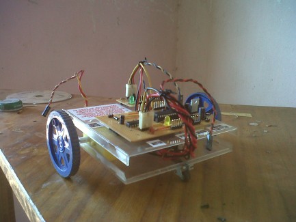
Yeah so i decided to rewrite the whole thimg and provide more info about the bot. Currently LUMMY doesn't have any sensors that help him understand his sorroundings (ping sensors,motion sensors.etc ).It is only using an IR receiver which i took from an old VCR. I am using an arduino to receive and decode remote commands (also used to control an old VCR).
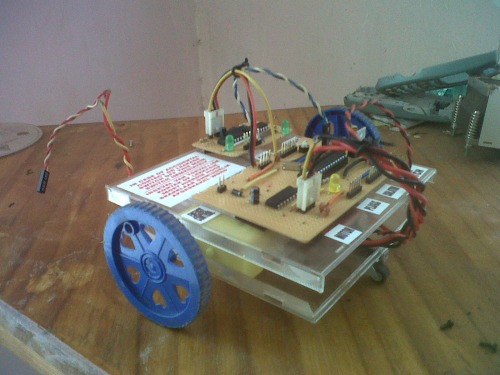
The first version of this bot had a breadboard on top with connections made by tons of wires running around. This was a good setup at first, but after a while I came to realize that a bot based on a breadboard isn't a good idea for two reasons :
If your bot bumps into a wall one or more wires may slip out their place and suddenly one motor is spinning at max speed and some LED's are lit
Breadboards are heavy, therefore add weight to your bot
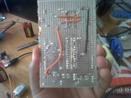
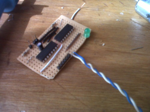
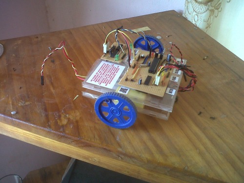
So, to solve the problem I had with the breadboard and tons of wires, I turned to veroboards. This was actually my first time ever using a soldering iron but the results surprised me. The results were a breadboard arduino and a motor driver (inspired by Mr. Oddbot's magician controller and Goduino ). This allowed me to get rid of the arduino clone which the bot used use as brains.
Extending I/o pins of atmega 328p
After Hooking up the motor driver, I was left with only 8 I/o pins on my arduino (not counting the Tx/Rx pins ). If theres anything that I learned over the years here on LMR is that hobby robotics shouldn't be expensive. So in order to extend the I/o (outputs actually) I turned so 74HC595 shift registers. There are lots of tutorials on-line showing how to hook up these to arduino, but they all didn't have what I wanted. They only showed how to shift in one byte of data at a time. This wasn't practical when I applied for my MA (Modified Arduino), because if I had 8 LED's and the where all
on HIGH state ( B11111111 ) and wanted to turn off LED number two and four I had to shift in new byte ( B10101111 ). In order to have control of individual pins of the register I applied my little knowledge of C- Language and used “Bit masking”. Where if I want to change the state of one bit in a byte I use :
REGa(data1 &= ~(1 << b)) for LOW state
REGa(data2 |= 1 << lenb) for HIGH state
Where 'a' is the register number ( two registers in my case, so can only take 1 or 2 ) and b is the pin ( 1 to 8 ). After all this I had additional 16 output pins that can be controlled individually by calling a function EPORTA_HIGH( 1);
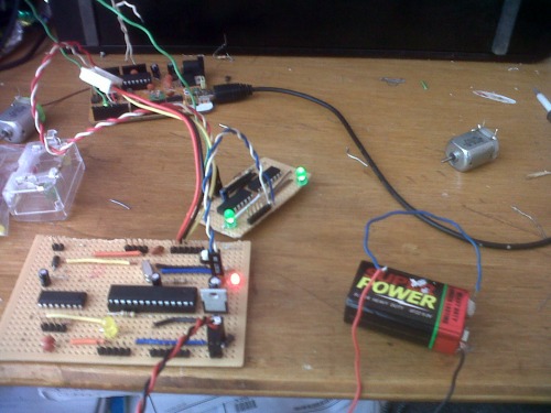
9v battery supply for motors problem
9v batteries for powering the motors is a very bad idea. My bot had only 15 unites of play time with the Chinese brand. They work fine at first but after few minutes they just stop delivering enough juice. To overcome this problem I turned to using old cellphone batteries rated at 3.7 v have two so that's 7.4 v . I just had to uncover them and remove small voltage regulation circuit and suffered few minor burns. Good things are that they were free, provide huge amount of current (bot had to run on 150 PWM) and last much longer.
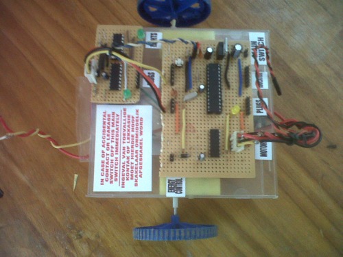
FINISHING TOUCHES
Now had an arduino platform using an ATmega 328 having 16 output pins and 7 input pins. Wrote a library for all the modifications. Tested the bot using IR library and an old remote and it everything seems to work fine now all that's left is to get some sensors ( Dagu compound eyes) and give it robot behavior.
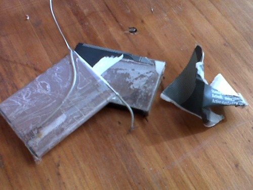
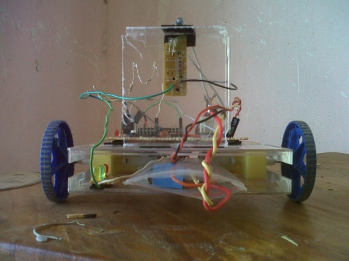
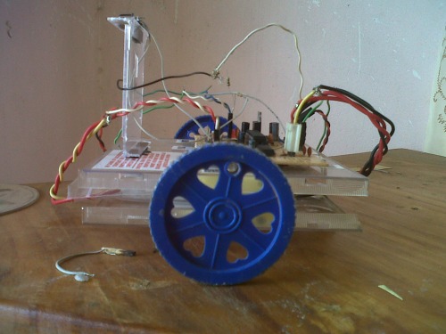
At the end I'm just glad that my bot went from this :
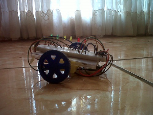
To that
UPDATE : 08/12/2012
About time I gave Lummy vision. It now uses Photo-transistos salvaged from an old printer.
Improvements :
1. No longer programed using arduino language but now uses C (transformatiion wasn't easy, but thanks to a lot of tutorials online about programming Atmega in c this was accomplished )
2.Can now avoid obstacles ( only in dark conditions as theres high IR in visible light)
Will post a video soon...
Avoids obstacles
- Actuators / output devices: Plastic geared motors
- CPU: ATmega328P
- Power source: 3.7v Cellphone batteries x2
- Programming language: C
- Sensors / input devices: IR sensor, IR LED
- Target environment: indoor