


Loki Bot
Loki Bot is my first design since completing the Start Here Robot. In many ways he is just a scaled up version but there are some differences as well. He's a sturdier design and will allow me to learn more about using the project board. I'm also using him to learn more about programming autonomous navigation. Like all projects, my making him I've already learned some things I will do different on my next bot!
The Body
The body is an outdoor electrical junction box purchased from the hardware store. The plastic is very easy to cut and drill though but it is also rugged. The body acts as a platform for the various pieces. The motors and wheels are attached to the bottom of the body. I was originally planning on having them inside the body but I found I liked having the bot up higher and mounting them to the bottom was easier as well. The only problem with this design is that the wheels and motors are attached to the access door to get inside so it makes it a little awkward to access the innards. The wheels are surplus baby stroller wheels. The attachment to the motor shafts needs improvement. The third wheel in the back is a rubber caster from IKEA that works great.
There is a retro taillight on each side of the bot in the photo at the top but not in the video. I've had some different thoughts on how these will function and at this point I am thinking they will be mounted more on the back corners and alternate flashing simply for syle and to show he is operating.
 The Head and Neck
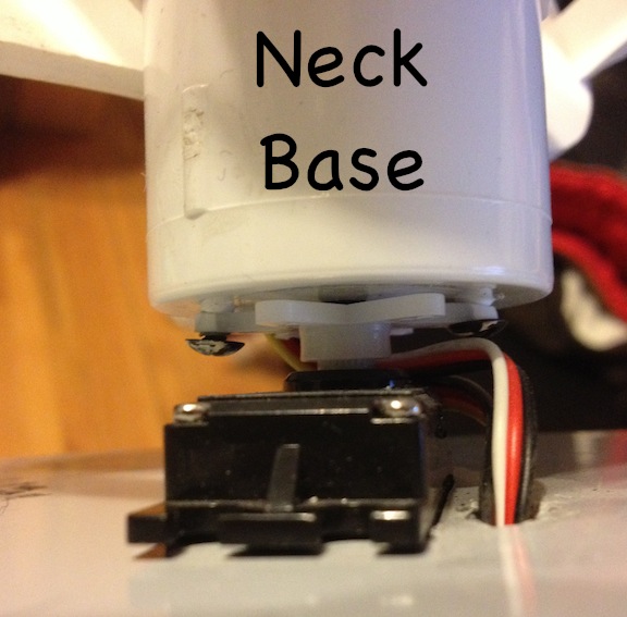
His head works with two servos. One way to think of it is in terms of pitch and yaw. The start here robot uses one servo to control the yaw or horizontal rotation of the head. This original servo is retained in this project and is visible as the base of the neck.The servo is sunk 2/3 into the body of the robot and attached to a PVC shaft to serve as a neck. I screwed the PVC piece to a multi pronged servo horn.
The PVC neck is actually 2 pieces that fit together which allows me to maunally adjust the rotational position of the head (see photo below). The servo wires and sensor wires from the head come down through the hollow neck.
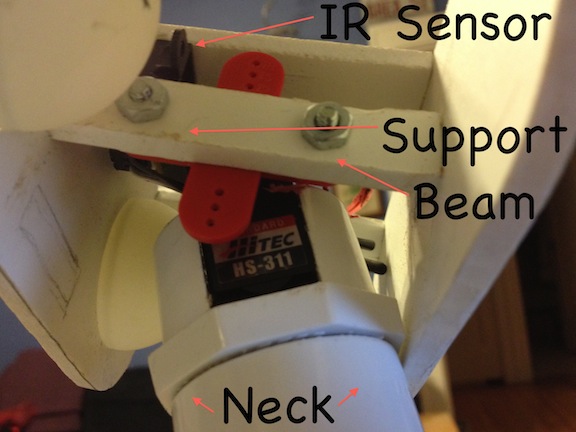 The working of the head is simple as well but was a little more complex to construct. The second servo controls the pitch of the head i.e. nodding up and down. As you can see in the photo it is attached to a support bar running through the middle of the head.
Using these two servos together gives many head placement options for not only sensing applications but programming personality as well.
Loki uses the same IR sensor used in the start here robot. It has been embedded in his forehead. His eyes are ping pong balls. They will eventually be lit by bright LEDs but that is a future part of the design. The head itself is all hand cut from a PVC craft sheet available at the local hobby shop. Right now everything is open to allow access but I plan on enclosing the head eventually.
I have a 10 segment red LED array that will function as Loki's mouth. You can see pencil lines on the inside of the head for where it will go. It is not currently installed as I am working on the basic movement of the bot at this point. I hope to have the mouth light up in unison with sounds at some point as he evolves.
Motion
The first video shows his autonomous motion. He has some trouble at the end with getting his wheels stuck on the door. I'm re-wrote his code to make him back up slightly before turning and this has eliminated that problem nicely.
Autonomous navigation of indoor environment.
- Actuators / output devices: 2 GM9 motors, 1 standard GWS servo, 1 standard Hitec HS-311 servo
- Control method: autonomous
- CPU: Picaxe 28x1 on Picaxe 28 Project Board
- Operating system: Picaxe
- Power source: 4 AA NiMH batteries
- Programming language: Picaxe basic
- Sensors / input devices: AIRRSv2 (Sharp GP2Y)
- Target environment: indoors