


Little Drum Machine
Here's my latest project. I liked Frits' Yellow Drum Machine so much that I decided I wanted to build one of my own. I'm working on the physical construction first -- once I have somewhere to mount the batteries and logic board, I'll glue on some drumsticks and start working on the drumming code. When my SRF05 arrives in the mail, I'll add that and start working on navigation. The last step will be adding the sampling board to record and play back sounds. Well, that's the plan, anyway :)
Photos
My brother is a woodworker, which is nice to have access to :)
Look at that, dadoes and everything!
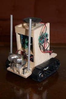
The robot's "superstructure," looking much nicer than the way I first planned to make it (Frits-style -- keep adding glue until it stops moving :). Batteries go in the bottom compartment, circuit boards in the upper one, and maybe a giant speaker glued to the top :)
Gluing it up...
The base so far
The underside
The breadboarded circuit. The blue board is a Pololu Micro Dual Serial Motor Controller for the main tank tread motors, and the three transistors will each switch one of the "drumstick" motors on or off. The green wire towards the top will be for output, maybe an LCD or a speaker.
One of the "drumsticks". I found that 1/4" aluminum tubing seemed to give a bit of a ring without being too heavy.
Sure, that's clear as day, right?
Main body glued together. It's a little taller than I had imagined, but ah well.
Rear view
2008/04/07
Reworked mounting of circuit boards to free up more space, and glued on the first drumstick motor.
2008/04/09
Now he's got a "bass drum".
Bass drum motor detail
2008/04/10
He can rock out now. Similar to what I assume Frits did, I hacked a little sampling circuit board, removing the pushbuttons and soldering wires to let the microcontroller trigger the playback and record functions. Now he can record his beats and play them back in a loop while he jams along with them.
Sampling circuit board detail
2008/04/13
My first PCB! A board for the SN754410 that lets me turn the sonar left and right.
The solder side. (I need a finer tip for my soldering iron)
Fabricated a bracket to mount the SRF05 onto the motor.
Rear view
He's now mostly complete. I want to add one more drumstick up front, but otherwise everything's there.
Once I'm happy with all the circuits, I'll probably solder it all up a PCB to eliminate that rat's nest.
Underside
2008/04/15
After gluing on the second front drumstick, I decided that the construction was complete, and I was reasonably sure that there wouldn't be major new components added anymore. So I decided to rebuild the circuit on a PCB "shield" that would fit right onto the Arduino rather than using a breadboard with dozens of loose jumper wires running between the two. To further clean things up, I cut up a ribbon cable from the same old 486 that donated its speaker to this project, and used that to connect my PCB to all of the sensors, motors, etc around the robot. The result is a much cleaner setup, and if I want to remove the Arduino for whatever reason, I can simply pull off the two ribbon connectors, rather than having to deal with tons and tons of wires and then later having to re-figure out which wires go into which I/O sockets. It took me quite a bit of thought to come up with a layout for all of the pins that grouped common functions together and made the circuit small enough to fit on that small PCB, and I'm actually pretty proud that I managed to fit it all in. What's even more amazing is that, after spending 6 hours soldering everything up, it actually all worked perfectly! I expected there to be tons of hard-to-track-down problems after doing so much soldering in such a small space.
One last shot of the circuit on the breadboard . I won't lie -- the real purpose of this shot was so that if I soldered up the circuit and it didn't work, I'd have some sort of documentation of what the original circuit looked like so I wouldn't have lost everything :)
That's a mess. Good riddance.
I didn't take any pictures of the soldering process, but here's the top side of the completed board. SO much cleaner. At the bottom is the 9-pin socket for the Pololu motor controller. Above that are the three transistors and diodes for the three "drumstick" motors. The screw terminals at the top are for the motor battery supply, and the pins on either side are for the two ribbon connectors. In the background, you can see the paper where I enumerated and grouped together all of the pins I needed to connect, in order to figure out what should be close to what, etc.
Bottom side of the PCB, where all the action is.
It slides right onto the Arduino, and mates with the Arduino's I/O sockets.
The paper where I laid out all my connections before soldering.
2008/04/17
With the construction done, I shifted my attention to improving the code. The coding I had done for playing drums worked pretty well for music that I hardcoded by hand, but as I started thinking ahead to how I wanted him to be able to 'write' his own drum beats, I realized that I'd need something a little more programmatical and less music-oriented. So I took a page from real drum machines, and I redid my drumming routines to get rid of the explicit calls to play notes of varying lengths. Now, instead, I just divide a measure into 8 beats, and my drum patterns are 4 measures long, so that's 32 beats per pattern. I have 4 "instruments" (bass drum, two drumsticks, and a click from the speaker), so a pattern can be represented by an array of four 32-bit long integers. When I want to play the pattern, I just loop over each bit in the integer, and play the drum if it's a 1, or don't play the drum if it's a 0. I had to do some fun bitwise math to look at individual bits from each integer, but it works, and now I just need to come up with four integers and I've got a new pattern.
I came up with some quick and dirty code to let him come up with his own patterns -- each time I measure left/center/right distance with the sonar, I stick each of those measurements into bass drum, snare, and hi-hat. It shows promise -- they actually sound pretty musical just like that. This whole 'coming up with his own patterns' thing will need some tweaking, to guide the patterns closer to musical and away from 'random banging', but it seems doable.
The part that I continue to have trouble with is the *&$king navigation. At first I thought I had found the problem when I realized that, since I had mounted my two drumsticks so far forward, my SRF05 was actually detecting those sticks most of the time when it looked left and right, so it was literally like he was wearing blinders. I cut the hot glue and re-glued the two motors angled farther back, so now that's not a problem anymore, but I still have trouble getting realistic numbers out of that sensor. Lots of times it will be like 8 inches away from a wall and pointing straight at it, and the sensor reports that the distances are something like (60 // 8 // 45) or (13 // 8 // 146) or things like that. The direction that is facing the wall head-on tends to work well, but the views to the sides seem to be completely unreliable. I added some debugging code to have it beep out the three distances through the speaker like the tracking devices in the movie Alien, with the pitch getting higher as the detected distance gets closer. That works really well for letting you know immediately how far away it thinks things are, at least relative to each other. And that has shown me that most of the time, it's getting totally incorrect numbers, which is why he can never manage to find anything to play drums on.
I know these sonar sensors have trouble when they're hitting a wall at an angle and things like that, so I'd expect little flaws every once in a while which wouldn't bother me, but this was pretty much just useless. Then I realized that one problem might be the fact that those little Solarbotics GM10 motors turn about 60 degrees in either direction, so his side views were actually getting close to looking completely sideways. That meant that, even if he's facing the wall head-on, the side views end up looking really far away, so the robot has to find himself really close to a wall before his side views can actually hit the wall:
So I glued small plastic tabs onto the motor, to limit the rotation of the head down to only about 40-45 degrees in either direction.
This seems to work MUCH better. I set him down on the ground, and he quickly lined up with the wall, drove up to it, and started drumming. Awesome. Now I can move on and continue working on improving the coding. So, some final shots of the completed robot:
The sampling board didn't have any holes in it for mounting with standoffs, so I borrowed more inspiration from Frits and just hot-glued it onto the side. And he's right, a strip of glue DOES work well to hold down the loose wires. How did I survive this long without a hot glue gun?
Ahh, I like that so much better than those loose wires everywhere.
I moved the microphone away from the bass drum motor, because it was picking up the whine of the motor louder than the drumming itself.
2008/04/19
I give up. The little plastic tabs I glued onto the sonar motor weren't working as well as I'd hoped, plus after just a few minutes of testing, they broke off and the motor went back to scanning its full 120-degree range. I just couldn't get the robot to find things worth playing on -- he spent all his time wandering around, snaking back and forth, never actually reaching any walls. It was especially frustrating since my 'object following' code for Harry The Discbot works so well. Harry, of course, has his "eyes" on a real servo, not a GM10 motor. So I gave up trying to get it to work with the GM10. I can certainly appreciate the pleasure of building complex things with really simple tools, but I just wasn't making progress and it wasn't being fun anymore. So a few minutes with an X-acto knife, and the GM10 is outta there. I first glued on the Hitec HS-55 micro servo that I'd bought on a whim to use on a later project. Once I started testing it though, I was surprised by how slow it was. I had just kind of assumed that, since it was such a tiny servo, it'd be really fast, but apparently it's geared down to be closer to the speed of a full-size servo. It worked just fine for locating objects, but I really wanted to try to preserve as much of the "zip" of the GM10 as possible. It probably doesn't help that the HS-55 is Hitec's "economy" model. When I looked up the specs, I found that sure enough, the speed of the HS-55 at 4.8v is 0.17 sec/60 degrees, whereas most of their nicer servos, just a few dollars more, are in the 0.12-0.14 range (and even down to 0.9-0.10 still at reasonable prices). There are $80 servos that do it in 0.04, but that's not what I'm looking for.
So I bought an HS-81, which is rated at 0.11 sec at 4.8v, brought it home, and tested it, and was much happier with the speed. It's still no GM10, but I'll happily trade a little bit of zip for actually being able to find the damn wall. So I broke out my X-acto knife AGAIN (I've gotten good at removing hot glue), removed the HS-55 and glued down the HS-81, and now we're in business. I ported over my object-following code from the Basic Stamp-powered Harry to the Arduino, spent some time adapting it to this purpose, and at last! He can actually reliably find things to drum on. Ahh.
With the GM10 gone, I no longer needed the motor driver PCB I spent so much time and thought making, so off that comes from the side of the robot. Ah well, I'm sure I'll find use for it in another project.
I've also made some more progress on his 'writing drum patterns' subroutine, so it sounds a lot more like music. I've posted a new video above showcasing his new talents. There's still work to be done, of course -- there's a slight gap between patterns for some reason, and I've got plenty of ideas for improvements to the code. But now he's finally starting to behave like a proper drum machine :) Now I'm having fun again. And I hope Frits isn't too disappointed that I gave up on the GM10 -- I'm impressed as hell that he managed to make his work so well with one. I guess I'm just not as skilled a roboticist as him :)
I'll keep updating this as I continue working.
Drive around and find interesting things to drum on
- Actuators / output devices: 2x Solarbotics GM3 for mobility, 3x Solarbotics GM10 for drumsticks
- CPU: Arduino
- Power source: 4 AA batteries for motors, one 9V battery for MCU
- Sensors / input devices: SRF05, microphone
- Target environment: indoor