


LineB
I started on a new robot. Totally thought up from my head. I thought of a line following robot that should be pretty easy. LineB or Line Bot. It uses kinda a lot of transistors and a compartor chip. LM393. I'm sure this should work.
So the robot runs of a 5V power supply so I built a 5V regulator circut.
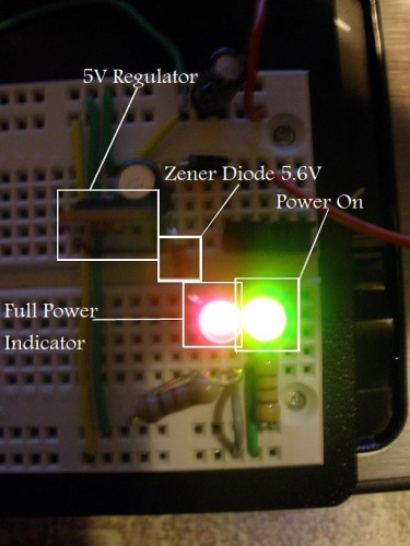
The zener diode is always on. When the battery falls below 5.6V the diode turns off and so does the LED. Telling you the battery is out of juice.
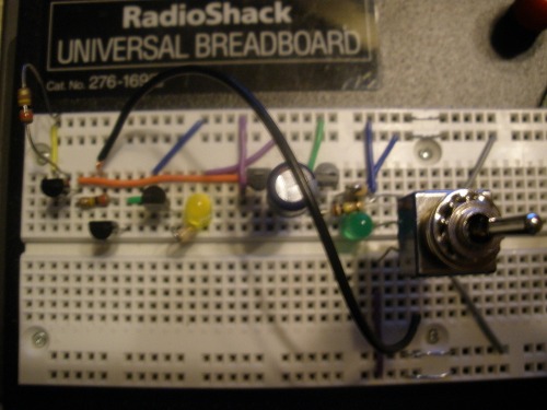
Sensor Circut/Inverter
The senso I bought coul only sense White lines on a black surface. The real problem was if there was not black surface or if there was no white line. So I had to come up with an inverter circut. Consisting of a bounch of transistors. the extra one on the far left is for replaceing the sensor becouse I haven't got it in the mail. :p
NonInverting
The Sensor is on. The Led is on.
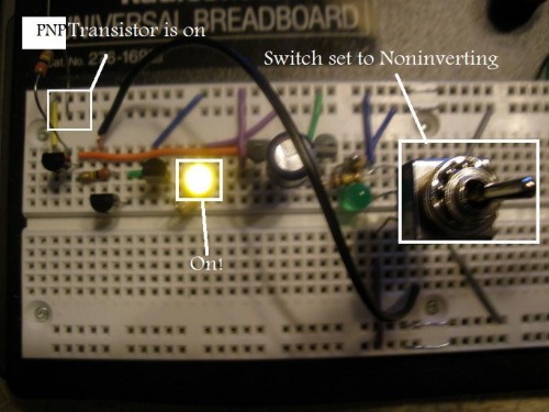
Sensor is off. Led is off. Simple!

Now comes the hard part.
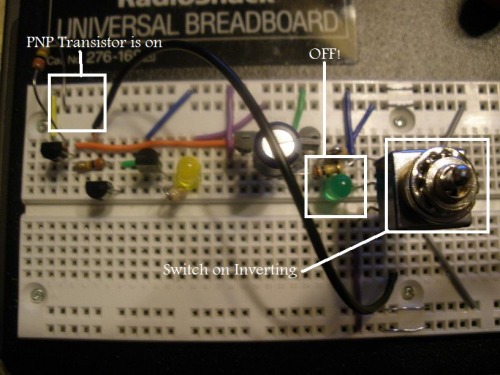
Inverting
This took me lots of thinking time until I thought that a capacitor could do the job of overiding the PNP transistor to turn off when the sensor is turned on.
The sensor is off. The Led is on.
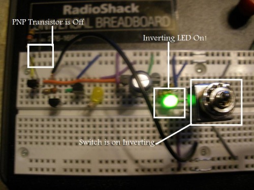
Senor is on. Led is off.
The LED's will be replaced and turned into inputs to the LM393. There will be a second circut like this for the left side. The output of the LM393 will power a transistor that will power a motor. :D
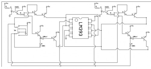
Here's the schametic of the circut above.
2/12/09
I started on a PCb because I really prefer the neat PCBs than the ugly point to point sodering. It's only half way done. The power supply indicators and chip are put in. just not the sensors and motor drivers.
