


line follower arduino robot with object avoid
hello guys...
this is our project...its called line follwer robot with object avoid using ultrasonic distance sensor...
soo..when robot will move along black track this time if any object is infront to this robot..then the robot will be stop...after remove the object from the black line,the robot can move to this black line...
black line tracked will be performed by two ir sensors and for object avoid ultrasonic sensor is used...
sooo lets start..................
Step 1:-components
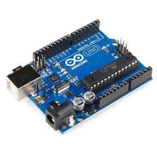
1:-arduino uno
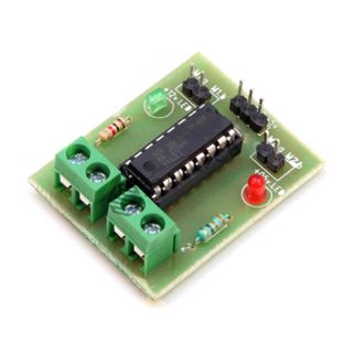
2:-l293d motor driver
3:-two ir sensor module(ir sensor array)
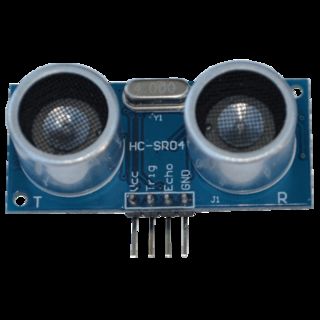
4:-ultrasonic distance sensor
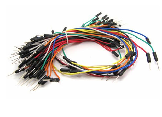
5:-jumper wires
6:-battery(power bank)
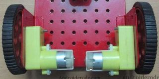
7:-one chassis
8:-two dc motors
9:-two wheels with caster wheel
10:-mini breadboard
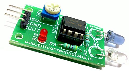
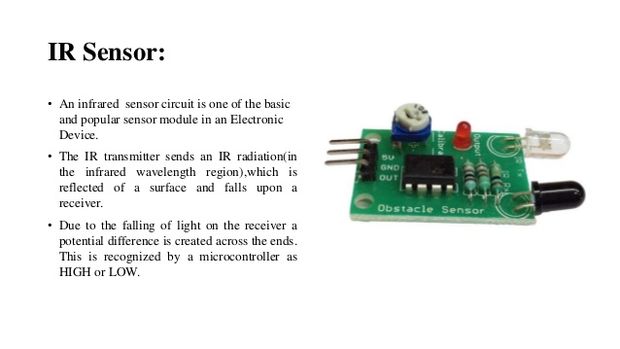
Step 2:-ir Sensor Connection
so
we have two ir sensors module...
left ir sensor and right ir sensor which have vcc,gnd and op..
vcc is connect to +5v
gnd is connect to gnd
op connect to pin of arduino
Step 3:-if You Used As L293d Ic
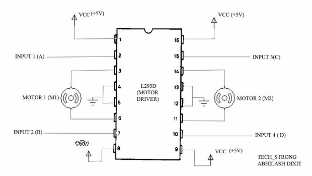
if you use l293d ic instead of l293d motor driver..
even its will be easy for connection....
l293d ic have 16pin... 1,8,9 and 16 pin connect to +5v.
and 4,5,12,13 pin connect to gnd...
input 1,2,3 and 4pin is connect to arduino pin..
output is connect to left motor and right motor..
input 1 and 2 is connect for left motor..
and input 3 and 4 is connect for right motor..
Step 4:-circuit Diagram
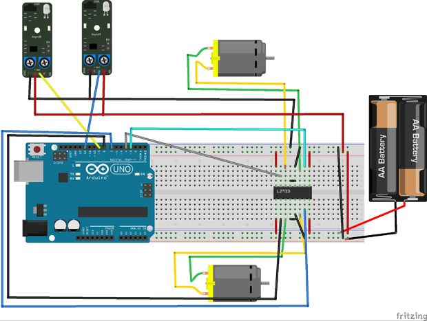
here..........
two ir sensors are connect 9pin and 12pin in arduino..
left ir sensor:-output is connect to 9pin of arduino
right ir sensor:-output is connect to 12pin of arduino..
for ultrasonic distance sensor :-
trig is connect to 5pin of arduino
and echo is connect to 6pin of arduino....
l293d motor driver:-
8,7,4,and 3 pin of arduino are connect to the motor driver.
8pin of arduino connect 2pin of l293d
7pin of arduino connect to 7pin of l293d
4pin of arduino connect to 10pin of l293d
3pin of arduino connect to 15pin of l293d
and vcc is connect to +5v and gnd is connect gnd.
power supply will be from battery 9v or power bank..
Step 5:-uploading the Code
#include
int x,y,t1=0,t2=0; unsigned int D;
NewPing sonar(5,6,15);
void setup() {
pinMode(9,INPUT); pinMode(12,INPUT); pinMode(8,OUTPUT); pinMode(4,OUTPUT); pinMode(7,OUTPUT); pinMode(3,OUTPUT); }
void loop() {
D=sonar.ping(); x=digitalRead(9); y=digitalRead(12);
if((x==1)&&(y==1)) { digitalWrite(8,HIGH); digitalWrite(4,HIGH); digitalWrite(7,LOW); digitalWrite(3,LOW); t1=0; t2=0; } else if((x==1)&&(y==0)) { if(t1>=20) { digitalWrite(8,LOW); digitalWrite(4,LOW); digitalWrite(7,HIGH); digitalWrite(3,HIGH); delay(500); digitalWrite(8,HIGH); digitalWrite(4,LOW); digitalWrite(7,LOW); digitalWrite(3,LOW); delay(1000); } else { digitalWrite(8,HIGH); digitalWrite(4,LOW); digitalWrite(7,LOW); digitalWrite(3,LOW); delay(500); t1+=1; } } else if((x==0)&&(y==1)) { if(t2>=20) { digitalWrite(8,LOW); digitalWrite(4,LOW); digitalWrite(7,HIGH); digitalWrite(3,HIGH); delay(500); digitalWrite(8,LOW); digitalWrite(4,HIGH); digitalWrite(7,LOW); digitalWrite(3,LOW); delay(1000); } else { digitalWrite(8,LOW); digitalWrite(4,HIGH); digitalWrite(7,LOW); digitalWrite(3,LOW); delay(500); t2+=1; } } else if((x==0)&&(y==0)) { digitalWrite(8,HIGH); digitalWrite(4,HIGH); digitalWrite(7,LOW); digitalWrite(3,LOW); t1=0; t2=0; }
if(D!=0) { digitalWrite(8,LOW); digitalWrite(4,LOW); digitalWrite(7,LOW); digitalWrite(3,LOW); delay(1000); } }
soooo...copy the code and paste in arduino..
lets start how playing this robot..
Step 6:-result
here....
this video link will be help you to make this project....
https://www.youtube.com/watch?v=v2ensg6H9A0
sooo follow our channel s_r tronics..thats help to build project...
so subscribe our channel to stay tuned with us...and gets new project also..
try to like and do comment in inbox...