


light following arduino robot
hello guys...this is our project
thats called light following arduino robot...
this project is based on arduino and light resistor.
A photoresistor (or light-dependent resistor, LDR, or photoconductivecell) is a light-controlled variable resistor. The resistance of a photoresistor decreases with increasing incident light intensity; in other words, it exhibits photoconductivity.
so lets start....................
Step 1:-components
1:-arduino uno
2:-jumper wires
3:-light resistor
4:-l293 motor driver(l293d ic)
5:-one chassis
6:-9v battery with battery holder
7:-two wheels with caster wheel
8:-mini breadboard
Step 2:-LDR Connection
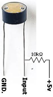
ldr have two pins:-
one pin connect to gnd
and another pin is connect to input of arduino.
even you connect it by 10k ohm resistor to +5v..
Step 3: Step 3:-if Used As L293d Ic

if you use l293d ic instead of l293d motor driver..
even its will be easy for connection....
l293d ic have 16pin...
1,8,9 and 16 pin connect to +5v.
and 4,5,12,13 pin connect to gnd...
input 1,2,3 and 4pin is connect to arduino pin..
output is connect to left motor and right motor..
input 1 and 2 is connect for left motor..
and input 3 and 4 is connect for right motor..
Step 4:-circuit Diagram
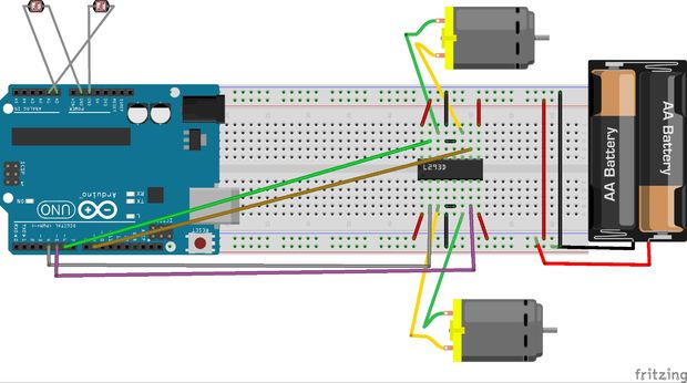
.here this circuit..
its connection so easy...at 1st
two light resistor one pin connect to arduino...and another pin is connect to arduino pin as input ..
this pin is connect to analog pin of arduino...
a0 pin of arduino connect to.......left pin of LDR..
a1 pin of arduino connect to......right pin of LDR..
L293D MOTOR driver:---
4,5,6,9 pin of arduino i connect to l293d motor driver.
4pin of arduino is connect to 2pin of l293d
5pin of arduino is connect to 7pin of l293d
6pin of arduino is connect to 10pin of l293d
9pin of arduino is connect to 15pin of l293d
and vcc is connect to +5v
gnd is connect to gnd ...to 9v battery
Step 5:-uploading Code
so guys below this code...copy the code and paste to arduino..
1st compile thenupload to arduino board..
int motor_left[] = {4, 5};
int motor_right[] = {6, 9};
const int RightSensor = A0; // Read the right sensor
const int LeftSensor = A1; // Read the left sensor
// Variable definitions
int SensorLeft; // This stores the value of the Left Sensor pin to use later on in the sketch
int SensorRight; // This stores the value of the Right Sensor pin to use later on in the sketch
int SensorDifference; // This value is used to determine the difference between the Left and Right
void setup() {
int i; for(i = 0; i < 2; i++){ pinMode(motor_left[i], OUTPUT); pinMode(motor_right[i], OUTPUT); }
pinMode(LeftSensor, INPUT); // Defines this pin as an input. The Arduino will read values from this pin.
pinMode(RightSensor, INPUT); // Defines this pin as an input. The Arduino will read values from this pin.
digitalWrite(A0, HIGH); // Enables an internal pullup resistor
digitalWrite(A1, HIGH); // Enables an internal pullup resistor
Serial.begin(9600); // Enables a serial connection through the Arduino to either USB or UART (pins 0&1). Note that the baud rate is set to 9600
Serial.println(" \nBeginning Light Seeking Behavior"); // Placed at the very end of void Setup() so that it is runs once, right before the void Loop()
}
// the loop() method runs over and over again,
// as long as the Arduino has power
void loop() {
SensorLeft = 1023 - analogRead(LeftSensor); // This reads the value of the sensor, then saves it to the corresponding integer.
SensorRight = 1023 - analogRead(RightSensor); // This reads the value of the sensor, then saves it to the corresponding integer.
SensorDifference = abs(SensorLeft - SensorRight); // This calculates the difference between the two sensors and then saves it to an integer.
// This section of the sketch is used to print the values of the
// sensors through Serial to the computer. Useful for determining
// if the sensors are working and if the code is also functioning properly.
Serial.print("Left Sensor = "); // Prints the text inside the quotes.
Serial.print(SensorLeft); // Prints the value of the Left Sensor.
Serial.print("\t"); // Prints a tab (space).
Serial.print("Right Sensor = "); // Prints the text inside the quotes.
Serial.print(SensorRight); // Prints the value of the Right Sensor.
Serial.print("\t"); // Prints a tab (space).
// This section of the sketch is what actually interperets the data and then runs the motors accordingly.
if (SensorLeft<500 && SensorRight<500) { motor_stop();
Serial.println("Stop"); }
if (SensorLeft > SensorRight && SensorDifference > 75 && SensorLeft>500 && SensorRight>500) { // This is interpreted as if the Left sensor reads more light than the Right Sensor, Do this:
turn_left();
Serial.println("Left"); // This prints Left when the robot would actually turn Left.
}
if (SensorLeft < SensorRight && SensorDifference > 75 && SensorLeft>500 && SensorRight>500) { // This is interpreted as if the Left sensor reads less light than the Right Sensor, Do this:
turn_right();
Serial.println("Right"); // This prints Right when the robot would actually turn Right.
}
else if (SensorLeft>500 && SensorRight>500 && SensorDifference < 75) { // This is interpreted as if the difference between the two sensors is under 125 (Experiment to suit our sensors), Do this:
drive_forward();
Serial.println("Forward"); // This prints Forward when the robot would actually go forward.
}
Serial.print("\n");
} void motor_stop(){ digitalWrite(motor_left[0], LOW); digitalWrite(motor_left[1], LOW);
digitalWrite(motor_right[0], LOW); digitalWrite(motor_right[1], LOW); }
void drive_forward(){ digitalWrite(motor_left[0], HIGH); digitalWrite(motor_left[1], LOW);
digitalWrite(motor_right[0], HIGH); digitalWrite(motor_right[1], LOW); }
void drive_backward(){ digitalWrite(motor_left[0], LOW); digitalWrite(motor_left[1], HIGH);
digitalWrite(motor_right[0], LOW); digitalWrite(motor_right[1], HIGH); }
void turn_left(){ digitalWrite(motor_left[0], LOW); digitalWrite(motor_left[1], HIGH);
digitalWrite(motor_right[0], HIGH); digitalWrite(motor_right[1], LOW); }
void turn_right(){ digitalWrite(motor_left[0], HIGH); digitalWrite(motor_left[1], LOW);
digitalWrite(motor_right[0], LOW); digitalWrite(motor_right[1], HIGH); }
Step 6:-result
here..
below this link follow and subscribe our channel s_r tronics to stay tuned with us..
also help you how to build this project easily..