


Lefty the MouseBot
I've started on my own version of the Herbie-stlye mousebot. They are so simple and fun, I couldn't resist.
So far I have the basic circuit breadboarded and working, and I've started on the body fabrication. My own customizations to this classic design will include:
- using a piece of the orignial mouse cable as a tail
- IR sensor module will cause bot to turn if it senses a signal from an IR remote
I'll make the tail by cutting off the 9-pin serial (yes, it's an old mouse) of the mouse cable leaving behind the strain relief. Then I'll pull two 22-ga solid core wires through the cable jacket. This will add stiffness so the tail can be positioned. The end of the tail may get an LED.
Introducing the IR module means that you can now direct the motion of this bot somewhat. When an IR remote (like from your TV) sends a signal to the bot, one motor will stop spinning, causing it to turn. When no IR signal is sent, the bot will work normally.
An IR module filters out the IR noise from the room, so it should prevent ambient IR from turning the bot when it's not getting a real IR signal from the remote.
Update 2009-08-03
I'm taking a break from the more complex SHR bot and getting back to Lefty.
Finished the physical build today, and ran a quick test with just the 9V battery hooked up directly to the two motors. They spin fast, but had no frictiion, so it barely moved. I used hot glue in a few layers to build up "tires". This worked fine, but one motor turned much faster than the other, so Lefty just turned in circles... to the right. Seems to be a theme with my bots so far. ; j
I decided to leave that alone and try to compensate with a trim pot in the circuit. I got all the components laid out and installed, but my first test prior to final assembly showed the circuit only let one motor run, and intermittently at that. I'll get back to it tomorrow. My brain is too sleepy for troubleshooting.
This is supposed to be my easy project. ; j
Update 2009-08-04
Well, in case anyone ever tries to base a mousebot project on the "Mousey the Junkbot" article by Gareth Branwyn, you should note that the printed article (available widely on the Internet) has errors in the schematic. The author provides an updated schematic on his website.
After fixing that the circuit seemed to work, so I buttoned up the little mousey and gave it a try. Two problems:
- The little toy DC motors I used move Lefty pretty slowly. I guess they are under-powered.
- The IR emitters used for eyes do not seem to be sensitve enough. They change voltage to the motor, but only just barely. They could be hooked up backwards. I'll have to check that.
So, Lefty goes back in his box for another night. I'm heading to bed.
Update 2009-08-20
I did a bunch of work on Lefty, but I'm just now getting to document it. I'm actually a bit stuck at the moment, and I've put poor Lefty on the shelf for when I feel like working on a brainless bot. There's something wrong with Lefty's circuit, even though it worked great on the breadboard. So I have to check over everything. Plus the motors I used turned out to be quite low power.
They worked great with 9V across them, but the circuit divides the supply voltage so each motor only gets at max 1/2 the supply. Lefty is a lot less active this way than in the video where I test the motors with just the battery. Oh well. Back to the drawing board.
The least I can do for Lefty is to document his construction, so here it is.
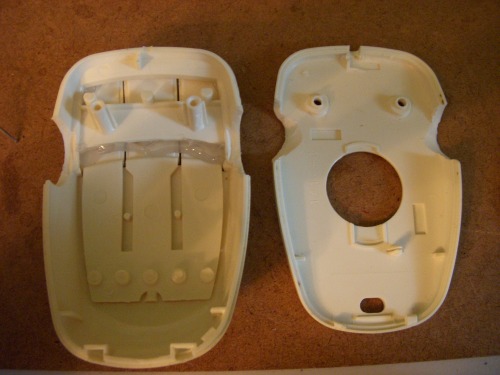
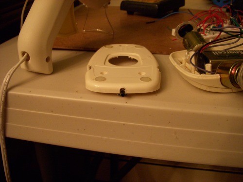
This is Lefty's shell. The old mouse I used was thicker on top and more slim on the bottom than most modern mice. So I had to Dremel a lot from the top as well as the bottom. This process involved a lot of cut-and-fit, cut-and-fit.
You can also see the hot glue holding the mouse buttons from moving around.
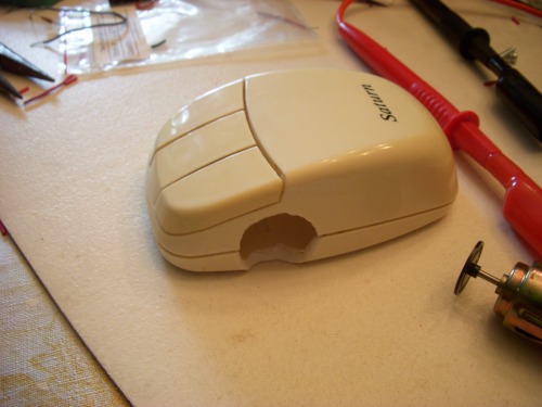
Here's Lefty with his shell closed.
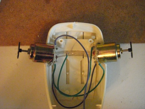
Fitting the wired motors.
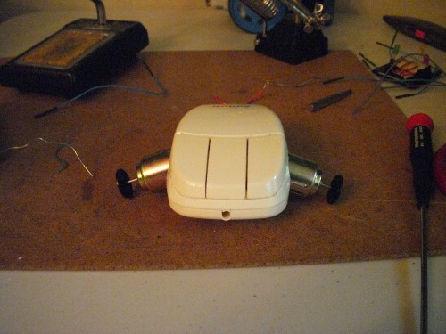
Here's the shell with the motors placed. The wheels are the optical encoders from the mouse.
As you will see in the video when I upload it, the optical encoder wheels did not have enough traction for how fast they were turning. So I made "tires" out of hot glue and patience.
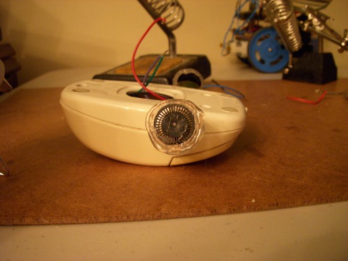
I hot glued a little button into the hole the mouse wire used to come out of. I had to Dremel away some interior plastic to make it fit.
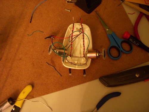
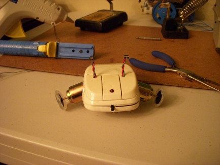
Here he is with the eye stalks in place. Those are the IR transmitters from the mouse on the ends. In this application, we use them as the light detectors.
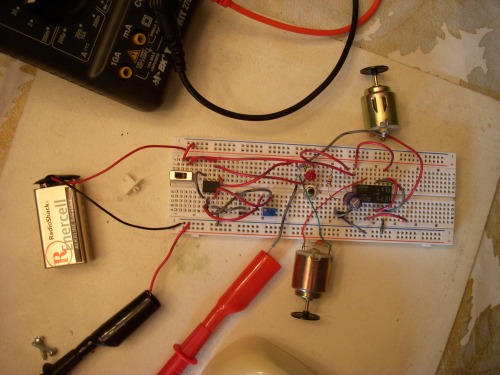
Here's all of Lefty's guts on the breadboard.
I don't know why I didn't take some pics of the interior with the components installed. Since I will eventually have to open Lefty up to fix him, I'll take more pictures then. This is it for now. Until next update.
At the moment, nothing.
- CPU: none
- Operating system: none
- Power source: 9v battery
- Programming language: none
- Sensors / input devices: front mounted bumper switch, IR transmitters for light detectors
- Target environment: indoors