


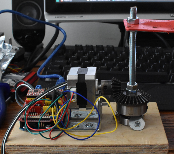
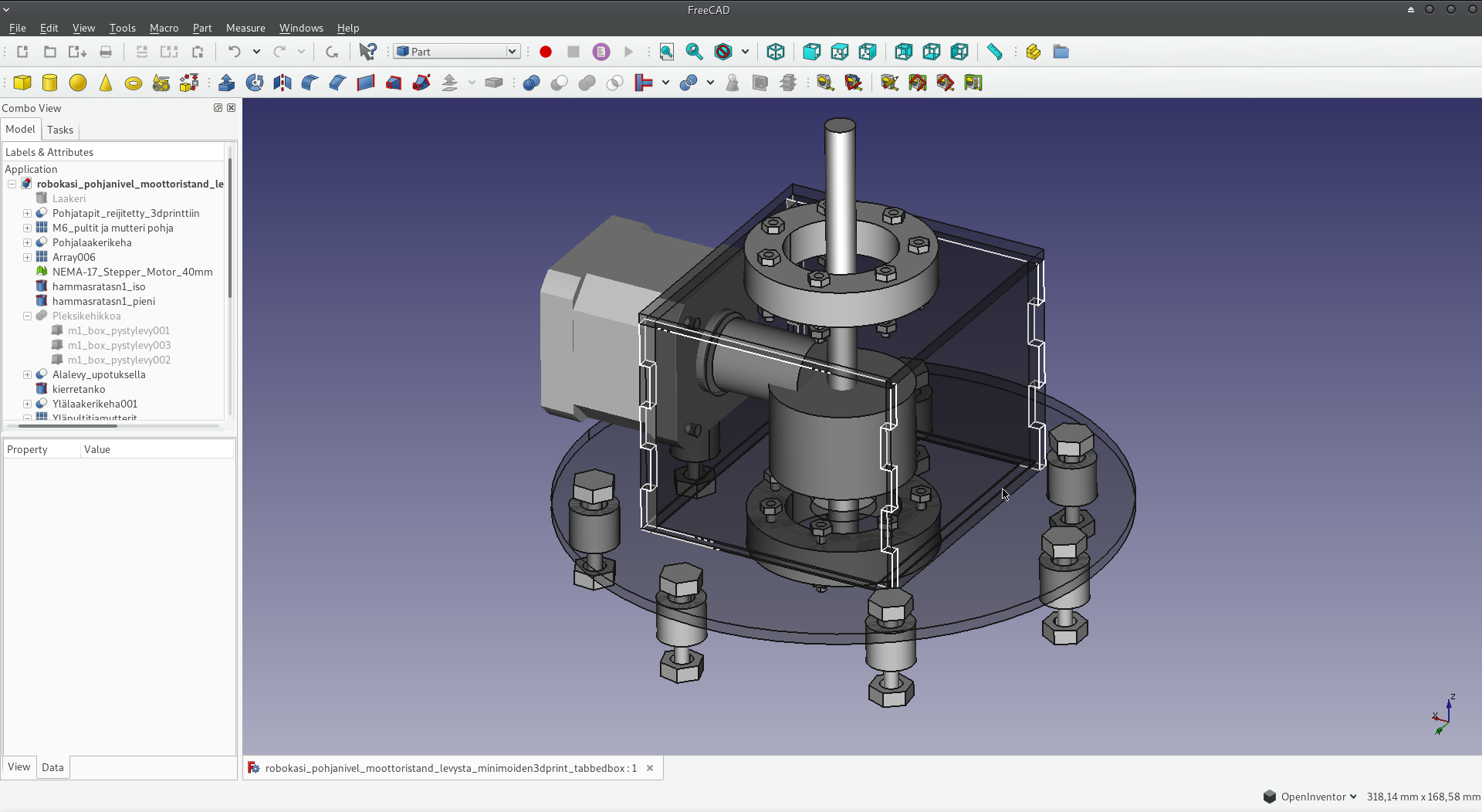
First model of the base joint is now functional. Using bevel gears, stepper motors, arduino uno -> cnc shield, and basic hardware (incl. ball bearing, screw rod). Made a fairly simple basic design as a proof of concept first to test microstepping with A4988 and inspect how bevel gear drive would work, and what kind of mechanical errors need to be taken in account.
While the arm is surprisingly solid, vibrations from the stepper motor transmit to the screw rod via bevel gears. I wonder if belt & pulley system would be be better, or maybe the bearing system also needs some work.
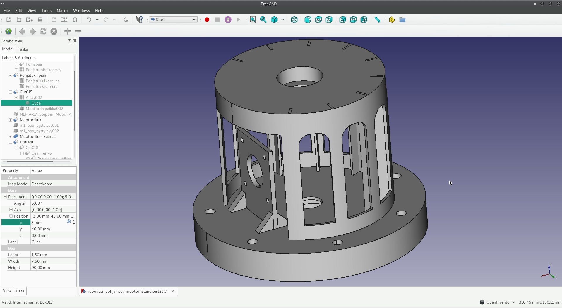
Designing the first joint on FreeCAD has turned out to be a challenge, but I've learned quite a bit in the process. Some drawings are simply illustrations of the ideas, and some thoughts on the complete plan, while some are revisions of the first joint. I've realized that some of my designs would have manufacturing problems (e.g. troublesome overhangs on 3d print), and I'd like to keep manufacturing as simple as possible, so I've tried to come up with a design that can be done with using cnc and laser cutting, keeping 3d printing minimized to save on production time and expensive filament. Each revision comes a bit better than previous, but I'm getting anxious to actually build something.
I laser cut the joint design at local FabLab, and assembled the thing together. It's really lovely how the parts fit together. It took two tries though, the first one scaled wrong (something with exporting from FreeCad), so I got miniature parts on wrong thickness, but the second time I was further guided at local Fablab that the pdf exported from Freecad can be tuned in Inkscape to achieve better result. Second time around, finished result was really nice. Material is 4mm plywood.
I thought I made the holes for bolts loose, but actually the bearing holder bolts (the circular plywood pieces) don't even have nuts, as they simply happened to screw tightly in place right away.. which helps because I didn't have proper length bolts anyway (either too short or too long). Installing the screw rod exactly in the center is a bit tricky, but it looks like it can be done with time. Currently I'm just happy I made something that works. I can't find obvious design flaws here, so I guess I have to move on to further joints.
https://youtu.be/HSZ8YRIRFHs
20.1.2019 Today I took a step to design something that I can try out. Designed all four joints with freecad, and made drawing and a techdraw for laser cutter. Unfortunately all three different ways of exporting a pdf/svg destroys the scale of the project, and when inspecting the result with Inkscape, I get strange measurements. What should be 30mm is now something in between 62-62mm, and other times the scale goes other directions. I haven't found any other 3d cad software for linux though, so the project goes back to sleep until I have time to troubleshoot this problem. It might also be that Inkscape's scale goes haywire. Anyway, no use to cut anything, as getting those measurements exactly right is absolutely necessary with this project.
22.1.2019 I still haven't found a proper way to do this, but I opened my drawing in Inkscape, and went on to measure few key parts, scaled by approximation method, until found a mythical scale of 5,67900. I achieved a precision of 0,1mm in scaling, which isn't really enough, but should do for prototyping. Annoying having to use workarounds like this though, but on the other hand, kudos to the open source developers for getting this far!
24.6.2019 I wasn't able to find any time on Mondays when local makerspace FabLab is open to public, so... Given that I had to find time to troubleshoot whatever's going on FreeCAD, I postponed the project, but thought about the design problems every now and then. Today, I finally got so frustrated of lack of progress, that decided to push the project one step further. One extra motivation was that FabLab is open during summer too, so maybe I can somehow find some time to cut this.. Unfortunately, no free Mondays in the foreseeable future.
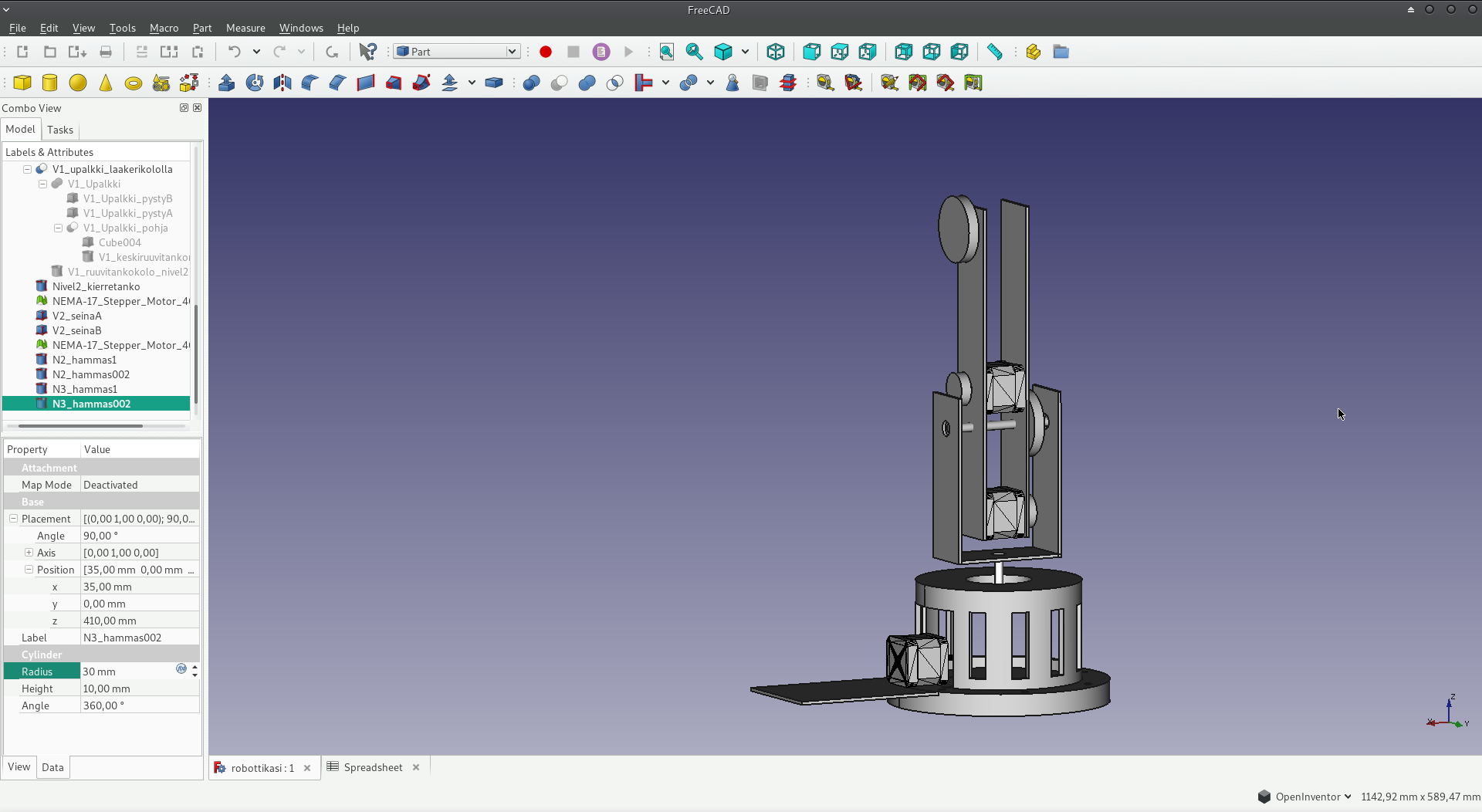
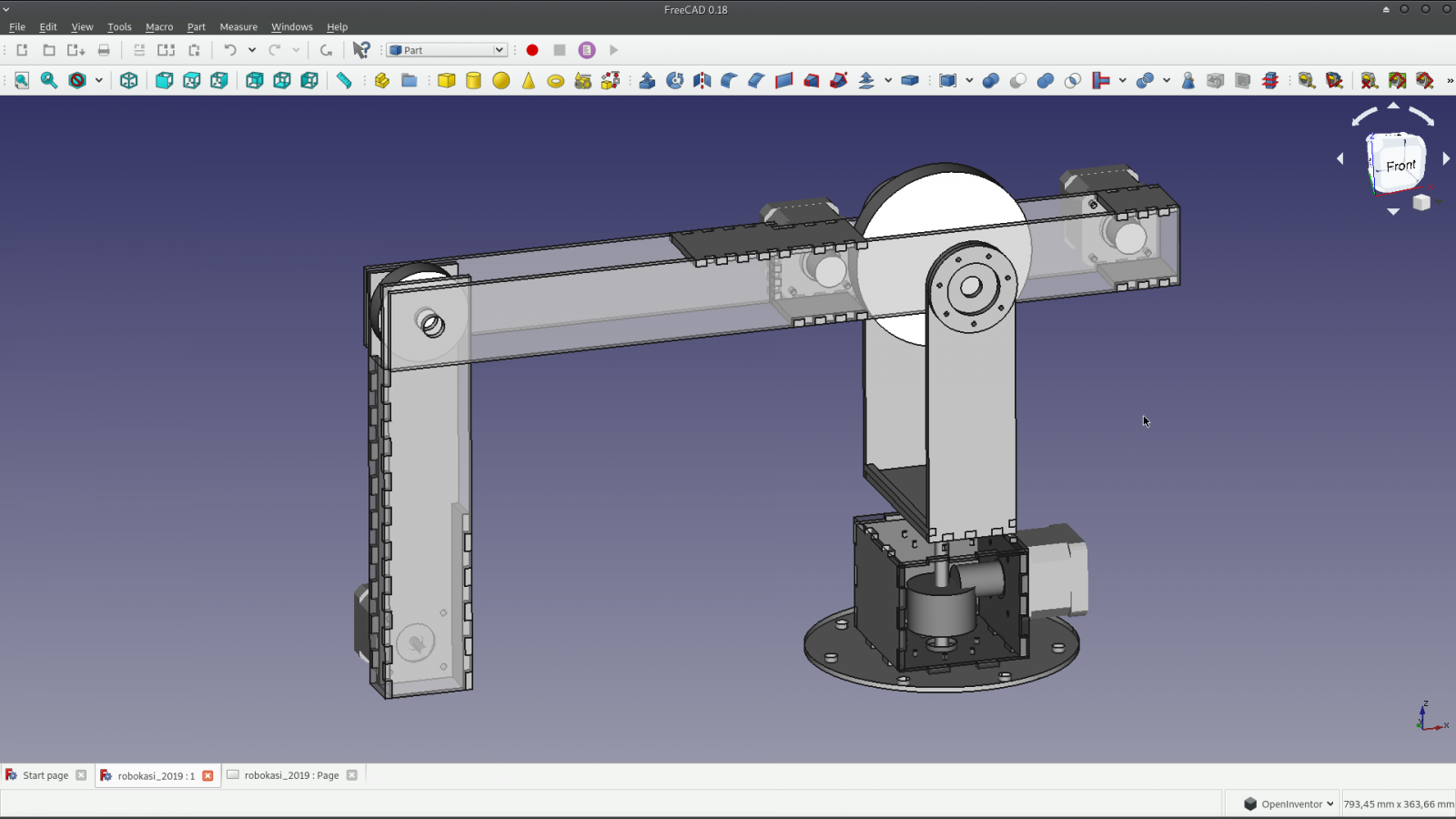
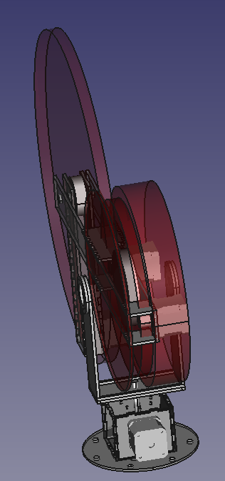
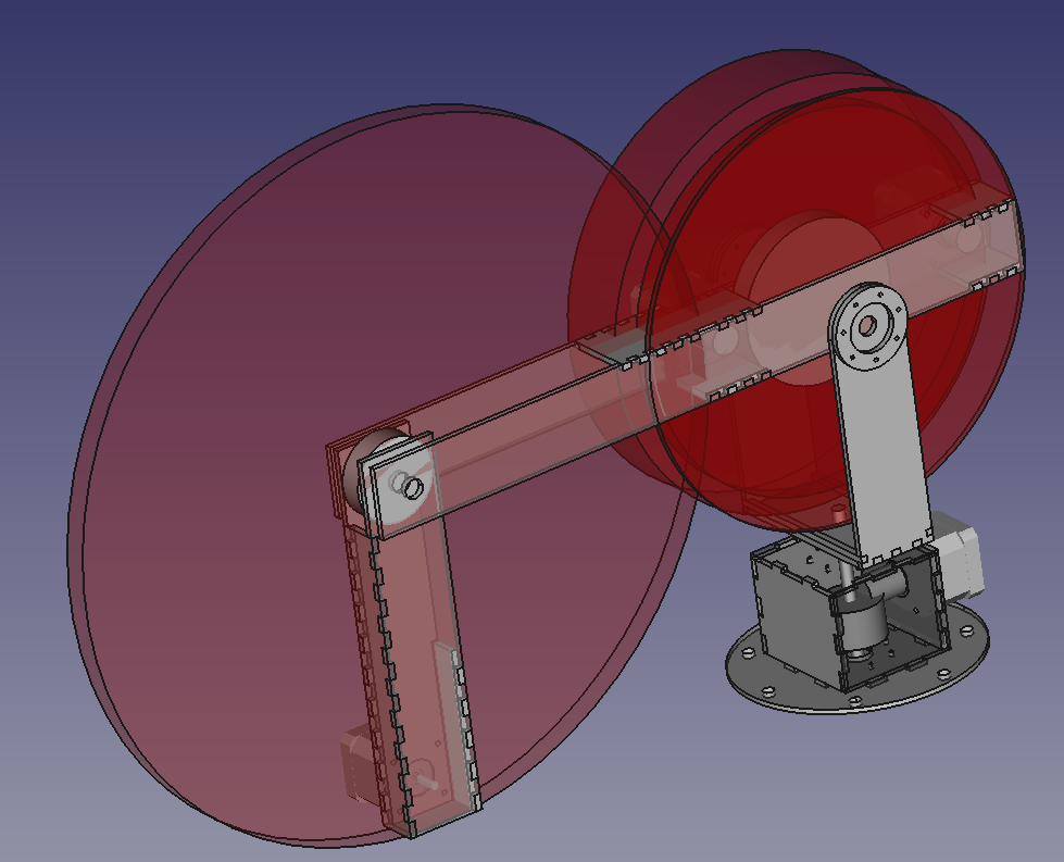
From basic blocks of box and cylinder, using union, cut and array functions, I got a design for 4 DOF arm. Also used some "virtual" shapes to reserve space for moving parts, like belts and pulleys. Tried really hard to get everything right this time (hole sizes, mechanical supports, space for moving parts, space for wires etc.). I'm a bit worried of physical stability, along with, well.. everything else... but that remains to be seen. It should work.
https://youtu.be/6TunWEhqO_0

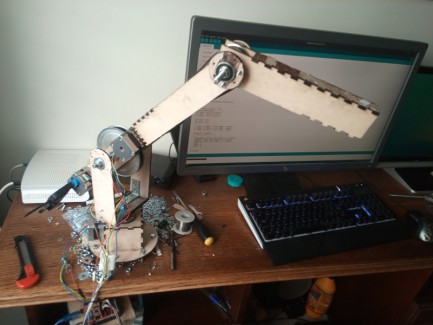
I was able to get some time from laser cutter at local FabLab, and manufacture the parts for a prototype. I was eager to build at least one version of the arm, just to get some idea of the problems I might be facing. The cutting settings failed to cut properly through, so I got quite messy result, even broke a few supporting pieces, but still enough to get a working prototype. I thought it's best to see how this works, redesign and fix design problems, then work more on getting a better manufacturing result.
My code works, I can control all of the joints from my computer via serial connection to Arduino. Motors turn like they should, and when the 2nd joint is turned upwards to minimize lever forces, I can move all of the joints of the arm.
Problems identified:
- Stepper motor torque for the big joint (2nd joint) is insufficient. It can just about hold the arm in place, but movement results in skipped steps and falling of the arm. The rated torque for the motor is 2,8kgcm (28Ncm) and the pulleys have a gear ratio of 1:6. There is obviously some energy loss at friction etc, I'm not sure how much, but without it the geared torque should be 2,8kgcm * 6 = 16,8kgcm. The weight of the arm that is has to lift is approximately 230g, and the length of the arm is 30cm, resulting in a torque of 6,9kgcm. I've set the VREF on A4988 to limit the maximum current to steppers to 0.4A and I'm using a power supply with a rated voltage of 12V (multimeter gives somewhere around 16V). I did also accidentally run the motors with overcurrent for a while, but they are still functional when tested without load.
- Belts tension should be adjustable, adjustable idlers are required. I now drilled a hole and inserted a screwdriver to act as a prototype idler wheel for the 2nd joint. It does work, but causes some extra weight and friction. On the other hand, 3rd joint has so little weight to lift that in testing it works even without idler.
- There should be holes for the tools that are required during installation of stepper motors. It's now nearly impossible to tighten screws, so I'm using clamps to attach motors for now. On the other hand, plywood is luckily easy to work on, so I could just drill the holes I need.
- There are some mechanical problems arising for unkown reasons. The first joint functions well without load, but when the arm is assembled on top of it, it starts to give fairly nasty sounds and shakes a bit, maybe something bad going on with the bevel gears? Second joint torque issues might be related to some mechanical disadvantages, friction, something I really have to keep an eye on. Also there was an obvious design mistake at where and how the axle of the 2nd joint should turn. For the third joint, friction is now enough to hold the light arm in place, and I can fasten the arm by using spacers, but I probably should decide on what sort of fastening I need here.
- The second joint is held in U-shaped frame, made of 4mm plywood. This structure, as anticipated, is way too weak. For the prototype I used corner irons to strengthed the design, but this is yet another design piece that should be improved.
- Stepper motors DO get hot!
- 4th joint motor is still missing, as well as a design for fastening a tool to the motor. I'm not sure if the Arduino CNC shield can independently control also that, or if I need another solution. It looks like the shield has functionality for X, Y and Z motors, and something labeled "A", probably for duplicating movement of some of the other motors.
- Plywood isn't straight, glued joints are imperfect. This is partly because failed laser cut, but also because of the gluing procedure I used. I probably should also design guiding pieces, like rectangles that I can use to hold the parts in place during gluing.
11.8.2019 Wrote some code quickly to see some basic movements. Not much to say here, code and video below.