


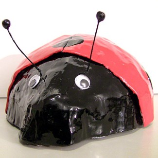
LadyBugBot clone
My LadyBugBot clone is finally finished. Or finished the second time because it got broken earlier. Now I kinda cheated and shot a new video of it running on a water heater (easier environment). If you are interested here's a link to the original LadyBugBot by isotope and here's a link to my making of LadyBugBot clone blog. The "special thing" about this bot is that it uses motors instead of continuously rotating servos (compared to the original). The problem then is the lack of output pins in 08M. To solve this problem I designed a circuit using the "tri-state" capability of configurable IO pins. This way I can control 2 motors (forward, reverse, stop) using only 2 IO pins. Motivation to do it this way was mostly to learn some electronics by designing something that actually works.
The recipe of this bot is as follows:
1 x Picaxe 08 proto board
1 x Picaxe 08M proc
1 x L293D driver
1 x DIL 16 IC socket
1 x 1N4007G diode
2 x BC327-25 PNP transistors
2 x BC337-25 NPN transistors
2 x 1K resistors
6 x 10K resistors
4 x 100K resistors
1 x Tilt twitch
1 x Micro switch (I used one with 37mm lever)
1 x Piezo transducer
2 x Solarbotics GM3 motors
2 x Solarbotics Gear Motor Mounts
2 x Rubber bottle caps
1 x 4xAAA battery holder (batteries not included ;-)
2 x Google eyes
3 x Block neodymium magnets
2 x Disc neodymium magnets
1 x Slide switch
1 x CD (preferably not having anything important on it)
Some aluminum tube (I used about 3cm of both 6mm and 8mm tube)
1 x Compression spring (choose one that will fit into larger tube)
Plus old news papers and glue for papier mache, chicken wire, iron wire, wire, solder, hot glue, contact glue and paint. Mix it all together and you are done (unless I forgot something). If you really need more detailed instructions keep on reading.
Electronics
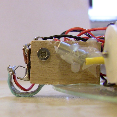
LBB clone is build on Picaxe 08 proto board. The proto board comes with all necessary parts to get it running but you have to purchase Picaxe 08M microcontroller separately. Assembling the proto board is the easy part.
Harder part is to put all components of the schematic below to the proto board: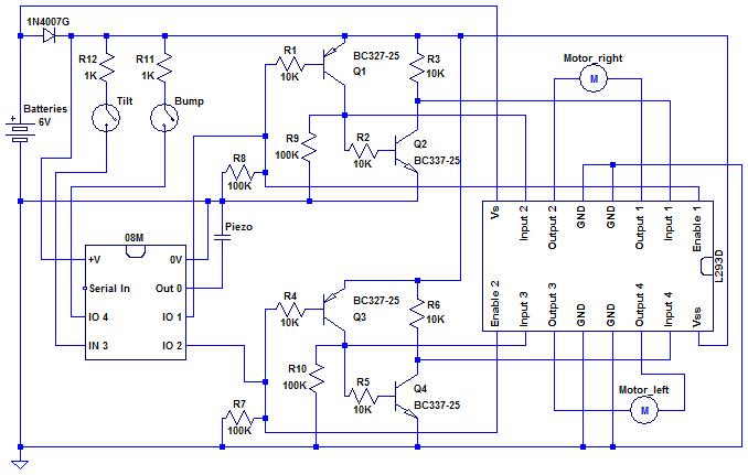
I'll try to explain how the circuit works. If you notice something weird or even errors you are welcome to comment/correct them. Easy part first: 1N4007G diode in the upper left corner is there to drop the voltage for the circuit a bit. If you are using 4 x AAA NiMH cells you don't really need it but when using fresh batteries the voltage can be over 6 volts and that might be too much for 08M. So just to be safe I added a diode in front of the circuit.
Tilt and bump switches are connected to 08M through 1K resistors. Resistors are not necessary (correct me if I'm wrong) but I wanted to be sure I don't fry the 08M if I accidentally set pin 4 low and it's connected to +V without resistor (creating a short circuit). Piezo transducer is connected to pin 0 and GND.
L293D motor driver is on the right. Its outputs are connected to motors as usual. Vs (supply voltage) is connected straight to the battery box and Vss (logic supply voltage) is connected through the diode to have same voltage level in both 08M and L293D logic. Inputs and enable pins have a kind of "special" connections and I'll explain that next with the tri-state part of the circuit.
So, now the "tri-state part" of the circuit. It the same circuit as in here but I added R9 and R10 pull-downs just to be sure that L293D inputs won't float. It seemed to work just fine without them (again, correct me if I'm wrong). The idea of the circuit is this:
- When the Picaxe pin 1 is low Q1 and Q2 are on. L293D's input 1 is pulled down by Q2 and input 2 pulled up by Q1 but that does not matter because Picaxe's pin1 is pulling enable 1 down. Motor_right is stopped when pin 1 is low.
- When the Picaxe pin 1 is high L293D's input 1 is pulled up by R3 because Q2 is off (because Q1 is off) and input 2 is low because Q1 is off. Motor_right is running is forward direction when pin 1 is high.
- When the Picaxe pin 1 is hi-z (tri-stated, high impedance) Q1 and Q2 are on. L293D's input 1 is pulled down by Q2 and input 2 pulled up by Q1. L293D's enable 1 is pulled up by Q1 base (voltage divider R1/R8).
- Picaxe pin 2, L293D's inputs 3 and 4 and enable 2, Q3 and Q4 work just like above.
I hope you got it (and I didn't make any mistakes when drawing and explaining the schematic). After you get it all to proto board it looks like this: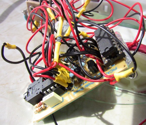
Yep. It's a mess :-) Notice that L293D didn't quite fit to the board so it's only partly there. No worries. You can solder leads straight to the IC socket for the half that doesn't fit.
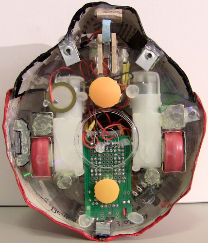
Bump/cavity and tilt switches are quite simple. I created the bump/cavity switch from a long lever micro switch by bending the lever so that it falls to cavities. I also glued some copper wire to the end of micro switch and soldered a wire to the lever so it would act as a bump switch too. Here's a couple of pictures that hopefully clarify the design: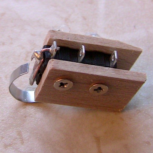
As you can see the micro switch is not needed if you bend the copper wire like I finally did. I started with the micro switch because I thought it would be an easy way to go and so the micro switch is still there. There's a piece of cloth glued to the lever to prevent scratching. The micro switch is wired so that it's open when there's no cavity and the bot doesn't bump into something. The tilt switch is glued to the side of micro switch and it's pointing a bit upwards so the bot would not try to "face upwards" when running on a table or other horizontal surface.
Wheels
Wheels are made of Solarbotics gear motor mount with pieces of rubber bottle caps acting as tires. The first time I cut a slice from the middle of the cap but I found out that it's difficult to get it to stay on the wheel. It just tends to slip off. I tried some universal glue and hot glue but it didn't hold.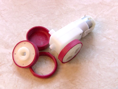
After the "unfortunate accident" (see the blog or video) I used the "closed end" of the cap as tire and glued it with contact glue. That seems to work very well. I didn't remember to take a separate picture of those but you can see the new tires on other pictures later any way.
Chassis
The first time I built the chassis I just measured how much space the proto board, motors and wheels would need and drew cutting lines to the CD. Then it was just dremeling until the motors and wheels fit. (R.I.P. old Ubuntu server)
The second time I tried Geir's tip and printed out a template for cutting. Then I just glued the template on the CD and again it as dremel time.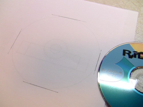
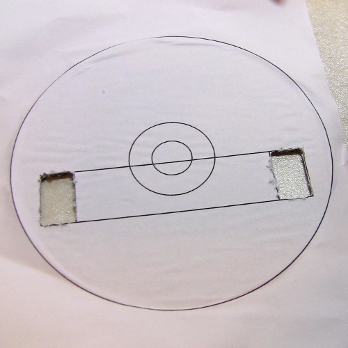
That worked out really well. After dremeling the CD it was time to glue motors on the CD.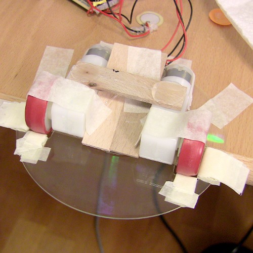
I used some tape and pieces of paint stirrers to help in aligning. Nice thing about the 08 proto board is that its width is almost exactly the same as two paint stirrers (at least the ones I have) :-)
Magnets
At first I used only three magnets but after the accident I added two more. Magnets are glued to CD with contact glue.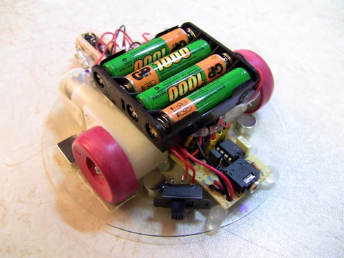
There's a magnet in front of wheels, behind motors and one is just over "the caster". If you are wondering why there are two casters it's because I found out that sometimes the bot "does a wheelie" if you press it down from the back. So the "second caster" is there to prevent "wheelie". It just has to be small enough so it would not "lift" tires off.
You can also see new tires and "nose support" (more about it later) in the pictures above. Oh and the piezo is there too :-)
"Shell"
The shell is made of papier mache (isotopes tip and my blog for more info). I created a wireframe model and wrapped it with plastic wrap.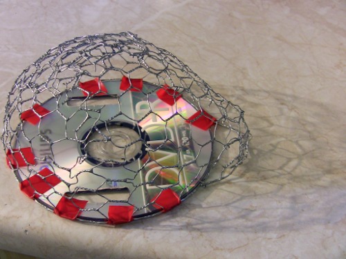
After "the first part of shell" dried I wrapped the whole thing with plastic wrap again and marked the line between "the nose" and "the shell" with tape. Then did a "second shell" over the first one. This second shell will be the real "openable shell part". The picture below shows how it looked like after drying.
And here's a picture with the parts separated: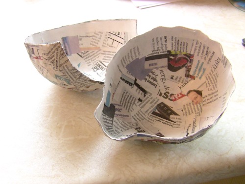
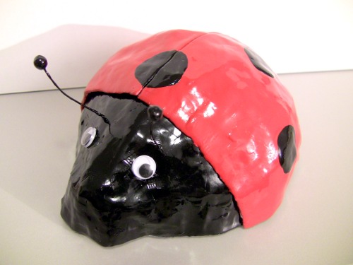
Now the "nose part" just needs to be cut to correct size. Then all you need is paint. I tried spray paint first (to the left over part of "nose part) but it looked really ugly. I ended up painting the body with this paint. (Sorry it's in Finnish. I didn't find the same page in English. I just hate web sites that have different structure for different languages.) Colors I used were signal red and black. It looks really nice. (Pictures of finished bot at the end)
"Nose suspension system"
The nose part has a home brewed "suspension system" so it can move back and forth a little bit. This way the nose will press the bump switch and close the circuit.
The suspension system is made of two pieces of aluminum tube. One piece must fit inside the other. I used 6mm and 8mm diameter tubes. Put a compression spring inside of the bigger tube and make a cut to smaller tube (not all the way!) so you can use iron wire to prevent smaller tube from falling out. Here's two pictures that hopefully explain how I did it: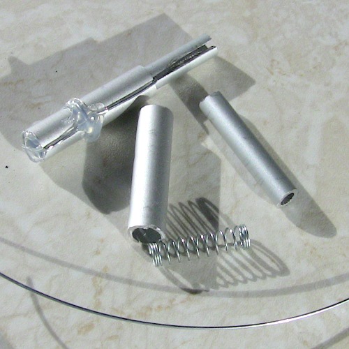
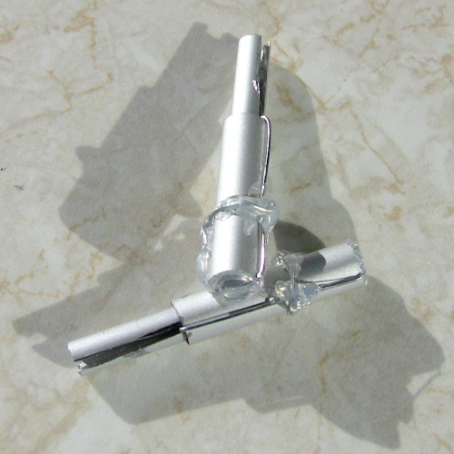
I made two of these but I only used one. Before gluing the suspension to the nose part I tested the placement with trial and error method and a lot of tape.
There's also two of these glued to the nose part: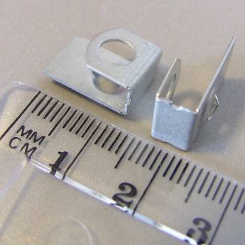
I don't know where I got those but they were together with some motherboard spacers in my misc. part collection. So maybe they came with a motherboard. I used some hot glue and cardboard to make them fit tightly on a CD. The idea is to give some support to the nose part. Here's how they are attached (sorry for a bit blurry picture):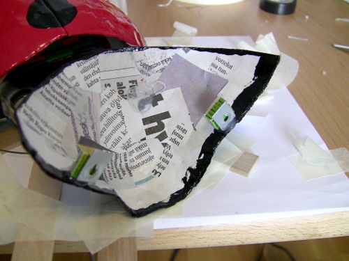
You may note that "nose support" is placed a bit differently in later pictures. That's because I changed the placement a bit after the accident. I forgot to take pictures of the attachment of nose suspension system but you can (hopefully) see the attachment in later pictures.
Final assembly
The shell is attached to the chassis by hinge. I glued the hinge to the chassis with contact glue and the shell to the hinge with hot glue.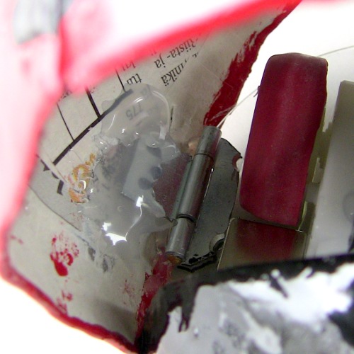
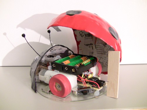
The nose part is attached from the "suspension system" to the front of the battery box (you can also see how suspension is glued to the nose part):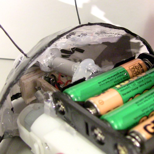
The shell part also has two support pieces (made from same things as the nose support). The one on the side also holds the shell closed together with the magnet in front of the left wheel.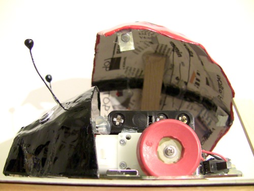
So that's about it. I probably forgot a lot of things here but you should get quite good picture of how this bot was made.
As future improvement (next generation LBB) there's at least better cavity/non-metal surface detection to be done. Also a tiny "paper shredder mouth" would be nice because lot of people hang their bills on the fridge door :-D
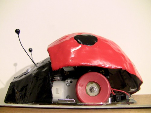
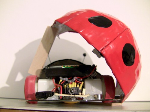
Here's just a couple more pictures:
Drives around on fridge door, water heater or table
- Actuators / output devices: 2 x solarbotics GM3 motors
- CPU: picaxe 08M
- Power source: 4 x AAA NiMH cells / batteries
- Programming language: Basic
- Sensors / input devices: customized microswitch
- Target environment: indoor