KITtyBot Mini
Final edit 9th November 2016: I think that I with the current code have achieved the goals of this robot. It moves fairly stable and predictable, see the second video, and I will bring these experiences with me to the next evolution of this concept.
Edit: Added a second video with updated walking gaits.
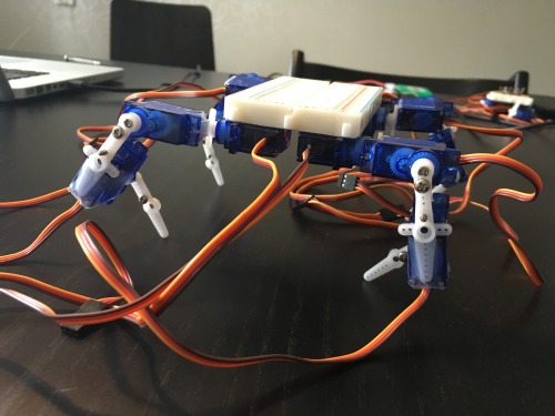
The idea from the beginning: Build a miniature version of my KITtyBot out of a breadboard and using the servo horns only. It is all powered by a small Arduino card (Pro Mini and Adafruit's Pro Trinket have both been used) using the sevo.h library. The first intent was to power everything with 3.7 V LiPo or LiIon cell, using 3.3 V versions of Pro Mini or Pro Trinket would make this possible. The servos are specified for 4.8 to 6 V but can work at lower voltages.
I used the Inverse Kinematics I developed for KITtyBot with some alterations (the most important being the "knee" joint pointing outwards instead of inwards). The code that earlier was relying on sending strings with serial data to the SCC-32 card now instead wrote servo commands using the servo.h library. 12 servos is the maximum servos that a Uno based Arduino can handle and that is what is needed. To control it I use a IR remote with a receiver on the robot (only occupies one pin on the quite "busy" Arduino card).

Things didn't go as expected though. The self adhesive on the back of the breadboard is strong but not enough to keep the servos in place. The same was for the servo horns. They are not stiff enough and flex too much to allow a predicable behavior of the robot. So limbs where designed and 3D printed. I managed to reverse engineer the splines on the SG-90 servo and make a fitting connection on my parts. I also made a body to which the legs and the breadboard are attached. Parts are attached to each other with self-adhesive tape.
It was possible to break out the pins from the Pro Mini (or Pro Trinket) ans also having 5V and GND to twelve male-to male pins on the breadboard and the attach the servo connectors to these.

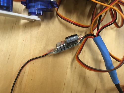
Power was the next issue. 3.7 V proved to be too less. While going fine under no load the weight of the robot was enough to make the servos lose control. The next step with Lithium technology is 7.4 V which instead exceeds the specification for the servos. So a power regulator is needed. Adafruit has a good UBEC (normally used on R/C models) that delivers 5V/3A. The battery I chose has no protection circuit so I used one of the (few) analog ports (left) on the Arduino for this. The voltage of 7.4 V must be divided by resistors to facilitate the 3.3 or 5 V range. I used one 1k and one 2.2 k resistor for this (One can use even higher resistances, the higher value, the less power is wasted through this circuit).


So the project drifted from the very simple design to become slightly more complex. Still the budget for a complete robot should not exceed $100, provided that one can find access to a 3D printer.
The BOM (I happen to have a local shop that sells Adafruit products so most of comes from there):
1 Arduino Pro Mini
1 Half-size breadboard
12 SG-90 servo (or similar 9 g micro servo)
1 5V/3A UBEC
1x1k and 1x2.2 k resistors (to divide the 7.4 voltage and feed one of the Arduino analog ports)
1 TSOP38238 IR receiver
1 Remote control
1 7.4 V 500 mAh (provides 10-15 minutes of operation)


