


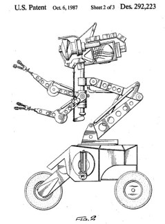
Jazzy The Robot Nearing Mechanical Completion
I have purchased, what I hope, will be a good base for my next robot. It is a Jazzy "Z" chair from Pride Mobility that I bought at auction for $27.50. This chair is smaller than the normal size chair and easily breaks down into 5 pieces for fitting in your trunk. It also runs on (2) 12 volt 12 AH gell cells instead of the huge heavy car batteries that most chairs require. Even though the chair is smaller and lighter weight, it is still rated to carry a 300# person at 8MPH.
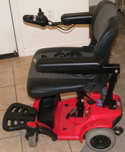
This is what the motor / brake assembly looks like removed from the chair. The brake comes off very easily with only 4 allen bolts to remove and the entire assembly comes off.
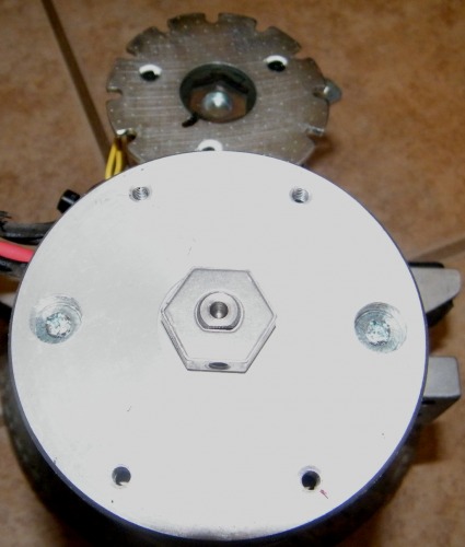
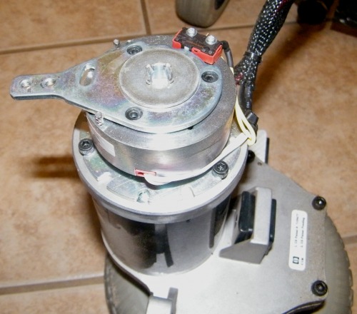
With the brake removed, you can see the hex head attachment that fits up inside the brake assembly to hold the motor in place with no power applied. A simple allen set screw holds it in place on the flatted shaft.

With the removal of the brake assembly, the motor can be checked for speed and current draw before it is re-attached to the chasis. This will provide a perfect mounting surface for a shaft encoder, which will be added a little later.
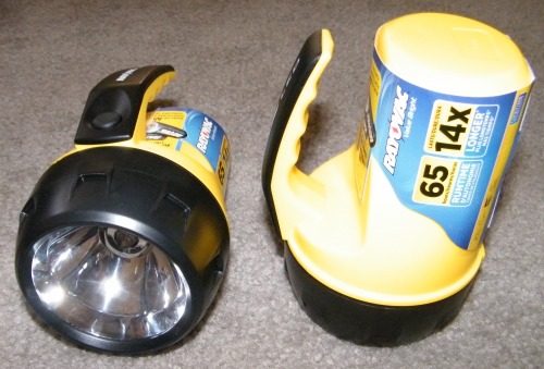
I've been working on the head but it took awhile to find just the right flashlights to use. These Ray-o-vacs were perfect. They are made of a very tough thick plastic that isn't brittle at all and they were the perfect size for my needs.
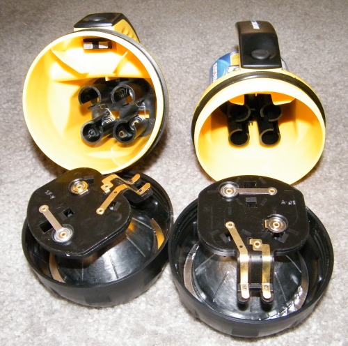
First order of business was to gut them.
After cutting off the handles, I put a bolt through where the handles used to be and used a standoff to support the rear.
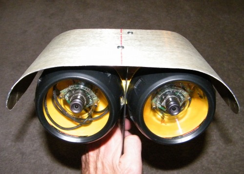
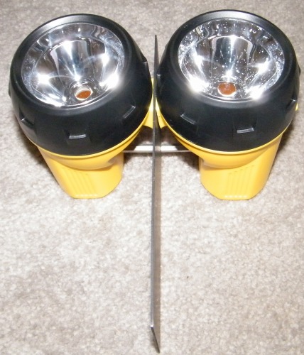
I removed the reflectors and fashioned a piece of gold anodized aluminum for the top of his head.
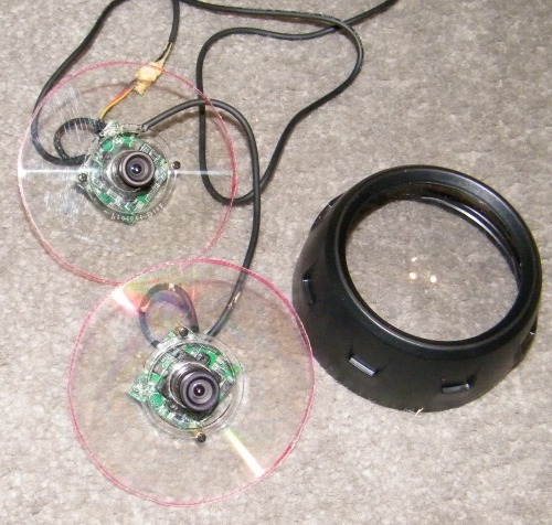
I needed a easy method to mount the cameras so they could be removed easily to disassemble the head section when needed. I used the plastic spacers that come in stacks of CD's & DVD's. They already had a hole in the center and they are easy to cut with a nibbler. I trimmed them down to the same diameter as the front of the flashlight so when you screw on the front lens assembly, it is held tightly in place. Next step is to decide on the covering for the disk, (so you can't see through to the back of the flashlight), and to mount the blue LED's around the circumference so the eyes will blink, (like Loki). I have a ball & socket to support the front of the head, (to provide 360 movement), and will use 2 servos on the back of the head for up / down, and tilt.
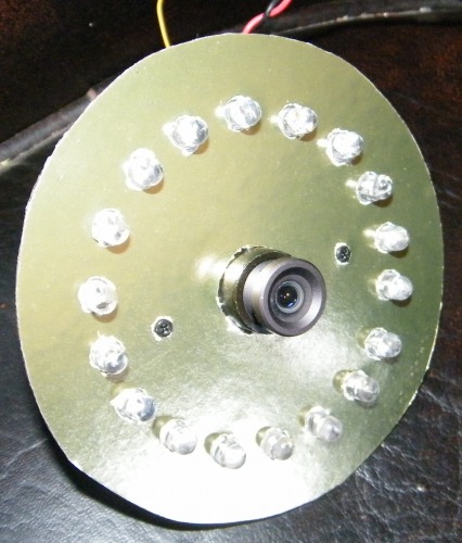
I covered the plastic with adhesive backed gold foil / paper and mounted 18 blue 5mm LEDs. I built up a circuit board with a LED bar graph driver IC. LEDs opposite each other are wired together so the lights will attack & decay from the bottom to the top to give it the effect of blinking, (like LOKI), thanks for the idea Dave.
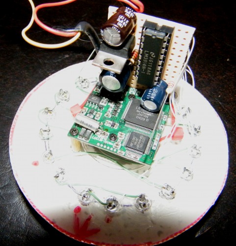
This is the rear showing the board for the video camera as well as the LED driver board. The LED board has an 8 volt regulator and some filtering to prevent problems with long lead power leads.
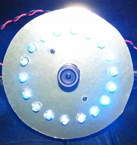
This picture was taken with a flash and LEDs full on.
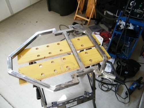
Well, I've finally got a good frame welded up and I can get back to work on "Jazzy".
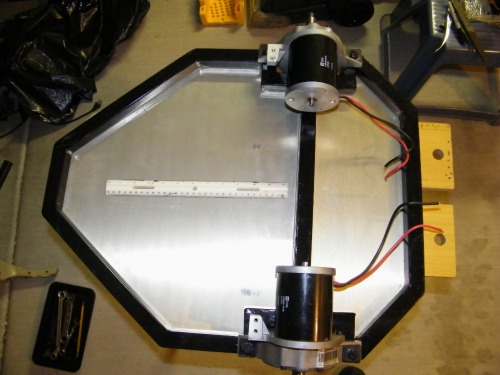
Bottom pan & motors attached.
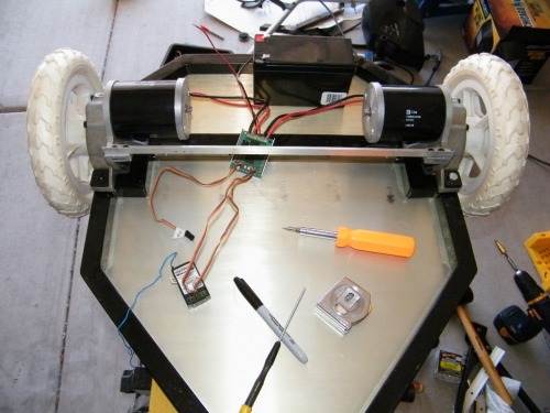
Got the wheels drilled, notched for the keyway, and mounted. Temporarily hooked up ESC, receiver, & battery to try out the setup. Things looking good, now I have to find a dolly wheel for the rear. The one I had is a little too tall and she doesn't set level.
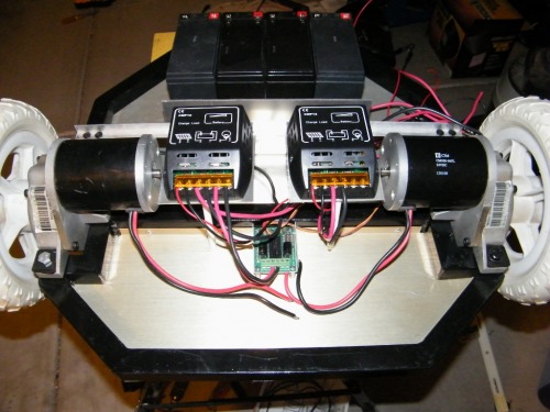
Power management modules, ESC, and battery box mounted and partially wired. Soon I'll be ready to start putting the body on her.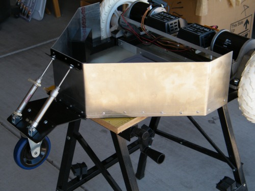
I got the rear caster wheel mounted, (with pneumatic cylinders no less), and the rear skirting attached.
This is a closeup of the rear caster arrangement and you can see the recessed opening on the left side for the power switches. This is so they don't get broken off or accidently tripped.

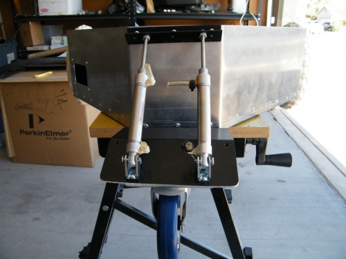
The knuckle has been welded, all the bearings have been mounted, and the linear actuator and struts have arrived. I still have to machine the mounting ends for the struts and the mount for the head & arms. Once everything fits & works as it should, I'll take it apart & paint it before reassembling it.
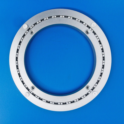
This is the 8" turntable I just ordered off Ebay to mount the body to the base. It looks like it'll be perfect and is rated to 300lbs. They are available in sizes from 4-16".