


Intelligent Vibrobot Mega
Update: 25th May, 2016
Omnidirectional infrared detection: Go to the bottom for further info, about the way to detect the habitat areas.
----------------------------------------------------------------
Update: 15th March, 2016
Solved issue: Escape from border/edge (go to the bottom for further info). Added video in real environment.
----------------------------------------------------------------
Intelligent Vibrobot Mega was a project started on September 2015 with several objectives:
- As a funny and interesting hobby.
- As a toy for my daughters.
- As an interesting thing to show friends.
- As a challenge to develope my own artificial intelligence algorithms in a memory constrained microcontroller and into a real environment.
- As a funny way to improve my skills and knowledge.
The purpose of the project was to create small microbots to live in a closed environment (habitat) like mice, hamsters or similar pets, and of course behaving intelligently.
First ideas
This was the first sketch of the microbots:
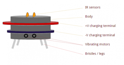
They could sense the environment with 360º infrared light intensity sensors and move within the habitat activating a pair of vibrating pager motors. Their legs would be toothbrush bristles, that could lead forward and rotational movements. Backwards movements would not be possible and hence they should have a rounded body, in order to escape from walls. Also, microbots must have external recharging terminals, for battery self recharging when needed.
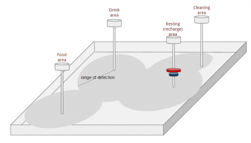
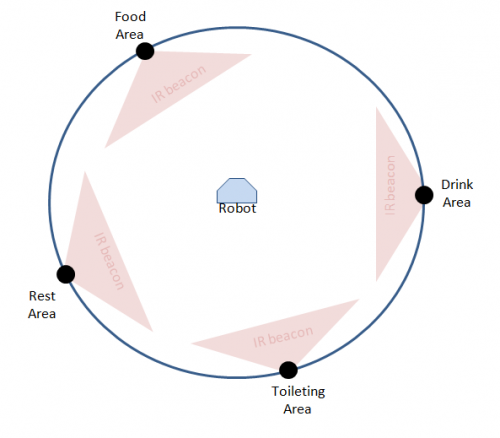
On the other hand, the habitat would be a closed environment with different areas, that microbots could detect (smell), like: food, drink, a toileting area and a resting area. Each area would have a 360º IR emitter, which emits signals that microbots could detect (smell) in a limited range, and act accordingly with different internal healthy needs.
This was the first sketch of the habitat:
Microbots behaviour
The first things I wanted to do were so simple:
- Microbots should have intelligent behaviour. So they should have something that could drive their actions: A healthy state.
- Microbots should learn to move in the habitat from experience, without previous knowledge about how to do it.
- Microbots should adapt to environmental changes in real time.
In a first approach I decided that this healthy state would be composed by different needs like:
- Hunger
- Thirst
- Toileting
- Fatigue
- Stress
- Curiosity
According with such needs, microbots could drive different actions or primary goals:
- Eat
- Drink
- Self toileting
- Rest
- Explore
Also, in order to have microbots with different behaviours, I defined an extra parameter that would modulate microbots' goals, which was: Personality. So, I decided that Personality could be composed by 3 parameters:
- Gluttony: this personality parameter will boost goals like Eat or Drink more often than average.
- Laziness: this one will boost Resting/Recharging against other competing motives.
- Curiousity: this one will lead to explore the habitat oftenly.
For that purpose I should design and/or use different Artificial Intelligence algorithms coded in Microbots' brains. These are the algorithms I've developed:
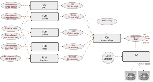
- Several Fuzzy Cognitive Maps (FCM): one FCM per healthy state, that takes: current and last microbot actions and current healthy parameters as inputs. And outputs an intensity degree (in percentage) of the associated goal.
- Other Fuzzy Cognitive Map (FCM), that takes: personality parameters and intensity goals degrees outputted by the previous FCMs, and outputs the next primary goal to be satisfied.
- A Reinforcement Learning Algorithm (RLA), that takes current "smells" from its sensors and the next primary goal to be satisfied. And outputs an action pattern to be applied to the vibrating pager motors.
Next figure, shows Microbots' brain architecture:
All this stuff, will be detailed explained in parallel blog entries. So, I will updating this main page with blog entries links, for those who would be interested.
The First Prototype
In a first step, I decided to use common material found in any laboratory, to build this microbots. So, for the very first prototype I used these materials:
- Nail
- Pager motors (from old and broken phones)
- SIL male connectors
- Super glue
- A piece of PCB board
- Several toothbrushes
- A pair of plastic rounded cases to bend toothbrush bristles, to boost forward movement (I will talk about this later).
- And, I bought these electronics components: IR light to voltage sensors, a LiPO battery, a small Cortex-M3 development board and an HC05 serial to bluetooth converter.
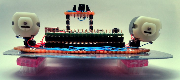
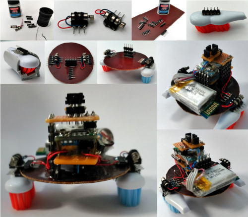
Next image, shows the building process of this first prototype.
After build I carried out several basic tests:
- IR Sensor detection: OK
- Motor activation at different speeds: OK
- Serial communications via bluetooth: OK
- Forward and rotational movements: FAIL
- Firmware execution: FAIL
- Movement speed: FAIL
The main problems with this prototype, were:
A) The toothbrush bristles, they were not properly bended to force forward movement. After reading a lot about vibrobots and similar robots, I found an interesting information carried out by a team of the Harvard University (see here) where they explains how bristles orientations affect to forward and random movement in vibrobots. The solution to get a forward movement consists in angled the bristles in the orientation of movement. That is the reason why I used a plastic case to bend the bristles. to angled them.
B) The Cortex-M3 development board used hasn't got enough RAM memory to run the AI algorithms and I need a powerful board.
C) Vibrating pager motors was so small to generate a proper speed movement, so I have to use a powerful ones.
The Second Prototype
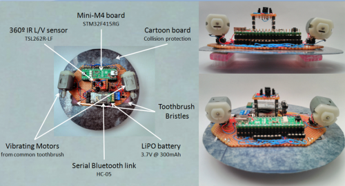
Knowing the limitations of the first prototype, I bought a powerfull board: a MINI-M4 dev board based on a STM32F415 micrcocontroller with 192KB of RAM and up to 1MB of flash. And I built a new one prototype for that board:
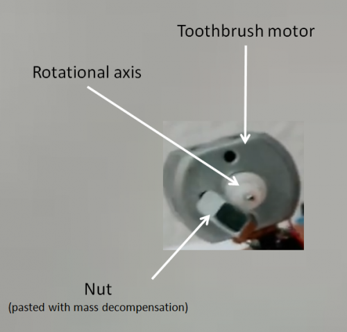
Also I broke a pair of old electric toothbrushes and extracted their motors. As these motors do not generate vibrations by themself, I glued a nut to the rotational axis but misaligned with its center of rotation, to create a mass decompensation and hence, vibrations.
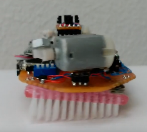
And I bought new brushes and in stead bending the bristles I cut them with a certain angle, to keep them straight but angled in the direction of movement. Look next figure:
And then I carried out again all the previous tests with result ..... OK!!.
This video shows Vibrobot Mega moving in a table and controlled via bluetooth.... drop included... oops!
The Simulator
Once all the AI algorithms were developed, I needed a platform to test them. As I was waiting to receive the new MIN-M4 board, in the mean time, I developed a simple simulator in which I could test these algorithms.
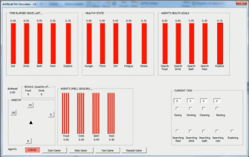
The simulator was a Frame with different fields, bars, a habitat region with its areas for food, drink, clean and rest, and in which I could check if the algorithms were working properly.
Next videos shows different tests carried out during the algorithm evaluation:
- In this video, each part of the Simulator is described and first evaluation is tested under ideal conditions, and even under environmental changes done in real time.
- In this video, a more realistic test is done. In this case, a gaussian noise is added to the motors action, simulating motor tolerances and imperfections.
- In this video, I add other realistic feature. In this case, a gaussian noise is added to sensor readings, simulating sensing imperfections, tolerances, etc...
- In this video, the most realistic, I add gaussian noise to both sensor lectures and motor actions. And even in this case, the algorithms work properly.
Real Tests
Ok, I've carried out first real envirnoment tests and I'm speechless with those unexpected results.
Free movement inside the habitat
In this first attempt, I've used an irrigation tube I had in the garage, to create a rounded habitat. Then I placed vibrobot inside moving freely, but here comes the problem (I'll upload a video next days). Once the bot touches the edge, it cannot scape from it. Even if it tries to rotate left or right, it only gets a forward sliding movement along the contour, unable to scape from it:
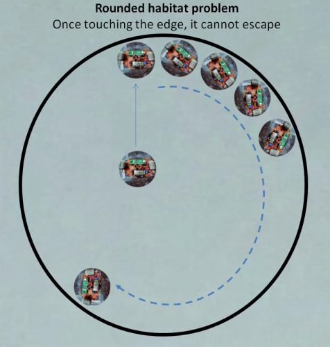
I thought that with a rounded body, the robot would rotate above its center and scape from the contour in any case, but I was completely wrong. I was wondering why, and what I think is happening, is that once touching the edge, the bot is unable to generate enough rotation force to escape from it. It starts rotating but at a certain moment, that rotational force is transformed into an undesired effect of sliding along the edge, probably due to the vibrating movement of the bristles with the floor.
Thinking about a cool solution for that problem, two different options comes to my mind:
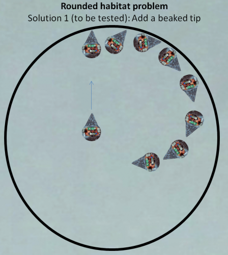
- Add a beaked tip to the robot. In that case, addind that tip, once it touches the edge it will start the rotation movement. Due to the tip length, its relative position to the edge would be more or less perpendicular, and now, the rotational force could be enough to go on avoiding the sliding efect... or at least is what I think could occur. This is the solution planned.
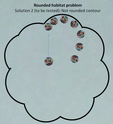
- Modify the rounded habitat in a "flower type" contour. With this solution, I could keep the robot as it is (with its rounded body). The new contour, is specially designed so that the robot could scape from it. In this case, even if the robot starts sliding, it will reach a place in which it stops touching it, and then recover the rotational force to scape from it.
Or perhaps, some of you have a coolest idea I could try....
I'll come back again in a couple of days with more results....
Update: 14th March, 2016
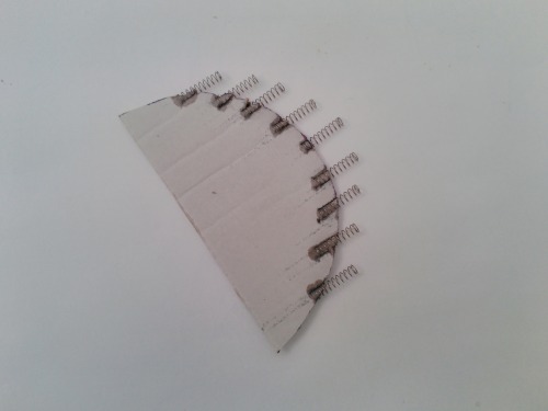
Well, finally I've found a solution to escape from the border. The solution: using spring bumpers that reduces friction forces against the border, and hence favor rotational movement.
Using the same rounded body (with a piece of carton) I've added several springs on the front side:
In this video you can see the difference between just the rounded body and the same rounded body with those spring bumpers.
In this other one, you can see the robot freely moving inside the rounded habitat (170cm diameter)
Next test: Omnidirectional infrared detection.... See you soon!!
Update: 25th May, 2016 Omnidirectional infrared detection
Vibrobot has an omnidirection infrared detector to estimate the distance between itself and the four areas in the habitat (food, drink, toilet, rest) and act accordingly.
Each area emits an infrared signal (beacon) that Vibrobot detects. However, as these areas emits the same IR signal, Vibrobot (by default) cannot identify the source, so a decoding mechanism must be developed.
These are the main problems that this mechanism must solve:
- Vibrobot can detect IR intensity from different areas and identify its source.
- Each area emits the same infrared signal (wave lenght = 940nm) during a predefined time.
- Signal intensity is limited in range, so if Vibrobot is on the other side of an area, probably it won't be able to receive the signal at all.
The first limitation to be solved, is that Vibrobot cannot identify the source of the received IR beacon. Then, as there are 4 areas (sources of IR), this emitting signal could be encoded in just 3 bits (with which could code up to 8 different values).
As Vibrobot scans its IR intensity detectors each 10ms, I decided that each bit of the 3-bit encoded signal would have a duration of 70ms. So, the 3-bit encoded signal will have a total duration of 210ms. And the bit coding would be similar to a Manchester coding. Next image gives an idea of the developed encoding.
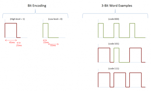
So, to identify the source of the IR signal, each area will emit a 3-bit word with different encodings:
Food Area code = 110
Drink Area code = 101
Toilet Area code = 100
Rest Area code = 011
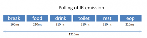
On the other hand, to avoid IR collissions, I decided to build a polling of emissions, so only one area will emit its 3-bit signal at a time. And this polling would be repeated continuosly.
Also, as Vibrobot could be far away from an area, and don't detect any IR intensity at all, I decided to add an extra IR beacon at the end of the polling. This new beacon I've called "end of polling", will be emitted by the four areas at the same time, so Vibrobot could detect it wherever it is. Its encondig is:
EndOfPolling code = 000
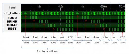
Now, in order to isolate consecutive polling emitting cycles, a "break" is inserted between them. During this break time, no IR emissions will be at all, and it allows that Vibrobot could get synchronized. Next figure shows the polling mechanism:
Next figure shows (view with a Logic Analyzer) two consecutive polling cycles and the 3-bit encoded signals from each area. As you can see, during the EOP (end of polling) all the areas emits at the same time.
Once Vibrobot can detect the source of the IR emission (decoding the 3-bit word), it can store the intensity of the detected signal, and then estimate the distance to that area. This estimation is ranged between 0% (too far) and 100% (too close).
Even if any area is not detected, when Vibrobot receives the EOP beacon, it can assing a value of 0% of intensity to the misssing areas. And then publish this information to other firmware modules.
On next entries I will add video showing a realtime detection of IR beacons.
See you!!
Intelligent navigation with vibrating motors and IR L/V sensors
- Control method: autonomous, Bluetooth
- CPU: ARM Cortex-M4
- Operating system: mbed
- Programming language: C++
- Target environment: indoor, Smooth Surface