


Initial Work on Rover 5
Am working on my first robot project - ie do something with the Rover 5 chassis Santa gave me for Christmas (2011).
Status:
Task 1 (done) was to get one of the motors going
Task 2 (done) get all of the motors going
Task 2A (No idea) work out what happened to my battery pack!
Task 2B (done) fix motor 3... or is it 4?
Task 3 (done) Get IR sensor and remote working, free rover from usb cable.
Task 3B test, and probably replace motor controller board.
Task 4 (in progress) calibrate the motors
Update: 30 January 2012: in which I get smoke.
Task 4 (Which seems to get further away the closer I get to it)
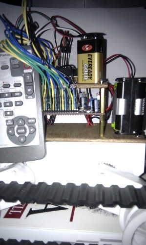
Over the weekend I wired up a switch, and secured the Arduino to the top mounting plate. This seems to have been my downfall. I also added a harness for the battery pack (ie some nylon ties) to stop it falling off the back.
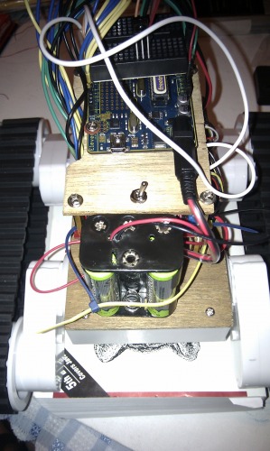
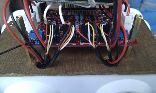
The picture above shows the new switch and the harness. Previously I had been connecting/disconnecting the wires. The positive leads from a 9v battery and the 7.2V battery pack are wired up to the switch, with their negative leads connected to ground. The DAGU controller manual says to connect logic power first before battery power. The switch throws both simultaneously, which will probably(?) not cause a problem.
I have earlier made a little progress on measuring the performance of the various motors by reading the quadrature information and using that to power the motors differently based on their calibration. I have taken readings for all four motors at pwm = 40. Tonight I did some readings of motors 1 and 2 at pwm = 200. I switched over the interrupts to read motors 3 and 4 and that's when the problems started. Because I had too much time on my hands I had screwed down the top mounting plate. This made the interrupt pins inaccessible (d'oh!) So I undid and pulled off the top mounting plate, switched the interrupts then started it up.
The motors moved very slowly and they sounded unhappy. I thought maybe they were dragging against the side of the "jack". I turned it off and reseated the robot, then started it up again. Same sound, also started to smell bad. I turned it off with the remote, the switch and pulled battery out, but something has popped on the motor controller board, letting off a small plume of smoke. :-( It looks as though when I undid the top mounting plate I pulled out the logic power by accident.
I haven't been game to power up the board again. Nothing on it has exploded, but I think that I can count 3 components which look odd - U7 (has a bump in it), T5 and T8 (looks a little glossy on the top).
Lessons learned
So the main lesson I've learnt is to design the layout so that the boards can be easily accessed - especially during prototyping. I will rework the layout on the top with a larger base mounting plate (ie overhanging the edges of the rover middle section. I have tried to think if I can mount any of the boards upside down within the rover base, but this doesn't seem to be possible.
The second lesson (?) is that apparently, it is ok to simply use the motor's battery pack to power both the Arduino and the motors. I am a bit leery of doing this as the Arduino needs 7V and, while the batteries produce 7.2V together, presumably this will decrease as they are depleted?
I know that I will need to get a mega at some stage if this is to have any awareness of its environment. I have also been thinking about getting pro boards, since once I include an Arduino in a project I am loathe to deconstruct the project to reuse it, and am probably paying a little more than I need to for new boards atm.
Task 1:
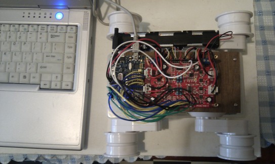
The rover 5 needs additional circuitry to drive the motors. This can be a dedicated board (I am using a Dagu 4 channel controller). In image 547 above, the Dagu controller is the red board on the right. The arduino (Uno compatible - a Freetronics Eleven board) is on the left. The second problem, after acquiring the Dagu controller, was that the controller uses pins, and I had no female headers. So initial work was with smart clips and bare wires into the Eleven's headers. This meant whenever I moved it one or more of the wires would come out. Without wires with headers and pins it would have been practically impossible to hook up all the motors.
I used this set up to get motor 1 running, stopping, reversing, stopping then repeating the cycle.
After this, I hooked up one of the quadrature encoders and counted interrupts - but am yet to calibrate the motor at all.
Task 2:
I could have bought some of these things, but that would have meant waiting a day or two for them to arrive. Instead I spent half an afternoon (first finding - no one had the headers, just bare metal sockets on a strip of 25, then) soldering up some of my own - this is a big waste of time. Don't do it. However, it did mean that I could wire up the grounds for each of the motors (there are four) to a single ground pin on the Eleven board. It also meant I got to play with lots of coloured heat shrink - neat.
The four wires coming to a single ground pin are visible in this photo. The colour coding here is: green for current sense from the motors, blue for pwm (motor drive/speed), yellow for motor direction, white for quadrature interrupts (the Uno only has two interrupts, so can only measure two motors at a time).
The bare Rover 5 does not come with any plates to mount the controller board on. The Dagu controller does come with ?brass? spacers though. The length of the wires coming out of the rover 5 are a little short, so the controller can't be too far away. I made a mounting plate from a bit of plywood (4mm I think?, although I have only fixed two screws so far). In theory you're supposed to be able to fit the battery pack in between the motors within the Rover base. This has the disadvantage that the batteries are not accessible if you want to replace them. For the time being I am keeping the batteries external to the Rover base.
I drilled two 14mm holes in the base through which the power connectors for the motors pass snugly. It made sense to pass cords up through one side of the Rover. At the moment the Eleven Board does not have a mounting plate of its own (it is resting on its wires), but I guess I will make another one out of plywood:
With that all done, I sat down and made a note of all the pins, then wrote some code to run all of the motors. Code is below. The rover is on a "jack" (actually a plastic component box which fits under the wheel base) with its wheels free to turn. A little trial, error and debugging got the code below up and running.
Now all of the wheels are turning and stopping in unison... Even motor 3. However, motor 3 seems to be wired up with reversed polarity, because it runs in the opposite direction to all the other motors. :-/
A quick look at the current output gave variances of about 30% between the motors. After a few cycles, the quadrature of the two motors I was measuring (1 and 2) was also out by a similar factor.
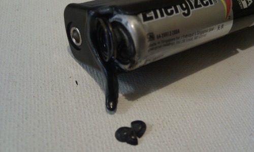
Well, that was weird. I left the work overnight. This morning I needed to get something from the box that was serving as the jack for my Rover. "How odd, where does this melted plastic come from?" I thought to myself, looking at the small blob of dried black plastic on the case. Then I discovered that the edge of my battery pack had melted. The battery in that spot also has some heat damage, and some melted plastic attached. I thought it must have been a short, but the batteries are all showing full voltage. Have not powered up the rover yet - who knows if I need another controller board...
So, today I went out looking for a new battery holder, as well as a set of NiMH (since they're supposed to be better for powering the motors - see my brain). No one sells 6 of course. Only 4 packs. I could also have bought 4 individually for the price of 8 in two 4-packs. Also, no one sells a 6 charger, only 4. It sort of works out ok though because the charger at home takes 4, but one of the slots doesn't work right...
I also want to make the robot IR controlled, and I had the idea of removing the IR receiver from an old panasonic movie camera which broke a couple of years ago. I did manage to identify and remove the receiver, but can't get it to work on the Arduino (that I had the wrong pin referenced in the sketch didn't help). I have probably connected the power pin up incorrectly and fried it by now, even if it was working after my ham fisted desoldering effort. So I'll have to buy one. I can get one from the local retailer for about $8, or, if I wait a day or two, by mail order for $2... or if I am prepared to wait two weeks or so, less than $1 - I've got some on order. I ordered late in the day, but hopefully I will get some tomorrow.
I have managed to find some time to sleuth the weird motor 3 issue. It seems that my Rover is wired in a way that is inconsistent with the Dagu controller:
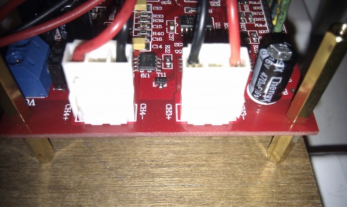
The connectors are biassed by the clip mechanism. They only go on one way. Of the four rover motors, only one of them is wired so that +ive red lead connects to the +ive pin on the Dagu controller (see photos above). That is motor 4 (?!) I guess I must have gotten my numbering mixed up? So I guess I can either snip them and resolder them (giving me red cords with a black end etc), or try to navigate the rear facing spike on the lead housings and ease them out and swap them over (would look nicer). Either way it will be a hassle.... Actually, using a little screwdriver it's pretty easy to push the pins out and swap them over.
Task 3 (see attachment: motor_IR_120126.pde)
tl;dr: have added battery pack + 6x NiMH, 9V battery snap and socket, mounting plate (plywood) for Arduino, IR reader and an old Panasonic remote control. Source code allows for forward and stop through the remote control, but can be easily extended.
Getting a Sensor
Have gotten a bit done over the past day or so. On 23 Jan I wanted to earn some hacking points by removing an old IR sensor from my dead panasonic video camera and hooking it up to the Rover. I got it off, but couldn't get it to talk to me (hacking points = 0, maybe -1 :'(.
So, I could have gone down the road and bought an IR sensor for about $8 (that's those expensive Aussie dollars btw - $8.40 US ;) but wanted to avoid the feeling of being ripped off. So I resigned to order some by mail order at 25% of that cost for a short wait and 12% of the cost for a long wait. I placed an order around 7pm that night and, amazingly, got my parts at 2pm the next day - including the cheaper sensors they said they had a 2 week lead time on (I bought a couple of the more expensive ones so I would have something to use till the cheap ones came in. d'oh!)
Parts: IR detector Panasonic PNA4602M, Vishay TSOP 4838
Decoding IR
Hooking the sensor up to the arduino and detecting ir signals took a matter of minutes (admittedly though I haven't added the smoothing electronics yet) guided by Ch. 10 of the Arduino Cookbook and using Shirriff's IR Library. The Shirriff library can also decode (not just detect) Canon IR remote signals out of the box (or at least it can for my canon remote). Unfortunately though, my Canon remote is for my current video camera and the Shirriff library doesn't speak Panasonic. I fumbled around trying to get some panasonic code posted by Wolfgang on Shirriff's site to work - that's 90 minutes I'll never see again! The good news though is that there is a code fork which supports decoding of Panasonic remote codes. I have lost my original link, but I think the fork is here.
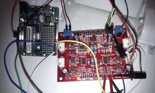
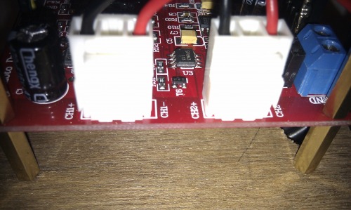
In order to print values produced by the Zenwheel code (ie forked code supporting Panasonic remotes), you need an additional routine to cope with the "long long" data type it uses (see printll() in motor_IR_120126.pde). Anyway, this was neat. It didn't take much to recognise every button on the remote (bar two - "record" and "A dub" for some reason, but I can live without them). They are now hard coded into the source. Woohoo - managed to reuse something -> +1 points. I was pretty impressed, as was my son. The IR sensor is the little black domed thing in roughly the middle towards the top of the picture above. The range of the IR sensor is impressive even without the noise suppression electronics that you're supposed to use - easily 4 metres, if not 6.
Hooking it to the motors
From there it wasn't much trouble to use the IR code to switch the motors on and off. If you were watching last episode you'd have known that I was having trouble with the how the power leads have been attached to the motors. I went and rearranged the cords so that each of the black/red wires attached to the -ive/+ive pins on the Dagu controller respectively. When I powered the rover up (using the remote control of course) I noticed that two motors (1 and 2) were rolling in one direction and two were rolling in the opposite direction, so I swapped the pins around on motors 3 and 4. Now they're all rolling in the same direction.
Mounting Plate #2
I began working on calibrating the motors, but this was about where the laptop ran out of battery. So I retired it and spent some time soldering a battery snap up to a socket and making a mounting plate (out of 4mm plywood) for the Arduino (haven't actually mounted it yet tho). The battery snap now frees the Rover from being umbilically linked by the USB cable. Because the leads coming from the direction etc pins on the dagu controller need a lot of clearance (probably from how I made them) I had to cut a notch along the side of the upper mounting plate. I am thinking about how I can arrange the boards/Batteries to fit them onto one level.
Roam Free
So far I had been running the Rover with the treads removed, and the wheels suspended. So I added the treads and, armed with my new battery snap, put the Rover on the floor for its first untethered manoeuvring (err... I mean repeatedly going forward and stopping). Untethered starting and stopping was a success. However, the tension from the treads tended to bow the legs of the Rover at its default extension. This, in turn, caused the treads to roll off after 40 cm or so.
After some consternation I managed to reposition the legs with lesser tension. The motor blocks have a flange on them which is caught by clips inside the base of the Rover. Removing (not just unscrewing) the clips frees the motors to be rotated (ie removed and replaced at the desired orientation). This is a neat locking mechanism. The treads have not come off at the lower tension.
I have been testing with the speed (ie pwm setting) at 40. When I crank it up to 200 (wow those wheels really spin!), the IR becomes much less responsive. I assume this is from electrical noise in the system (?) but maybe it could also be the larger number of interrupts from the quadrature encoders?
Am currently stumped in calibration, because my code seems to be doing something weird. I would like to get the motors calibrated before working on other stuff (backwards/turning etc)
Code
(see attachments for code)