Human Robot Experimental Platform
June 12, 2013
I used the Dragon Boat Festival holiday (3 days) to build a human robot experimental platform for various ideas I have in mind. The mechanical construction is not finished yet. On the right side of the robot will be a control panel with xbox 360 keyboard a custome made mini keyboard and a 20 x 4 LCD. I do not plan to add a second arm, but it's possible. It is very much WIP - like most of my projects.
All the aluminium parts are hand made from aluminium sheet with a thickness of 1.5 mm, cut with a special knife (or better scored and then broken apart) and bended on a piece of wood while fixed with a c-clamp. All the holes are drilled with a cheap battery drill; for the holes with larger diameter I have used a step drill bit.
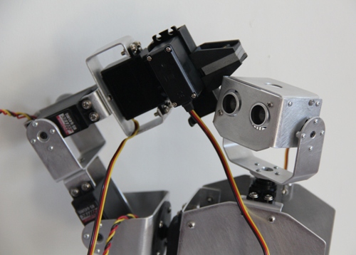
Closeup of the head and the gripper
June 14, 2013
As my xbox360 chatpat clone doesn't want to work with the library provided here and I don't want to spend endless time to figure out which protocol it has (if any), I decided to build my own mini keyboard to communicate with the robot.
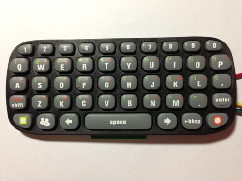
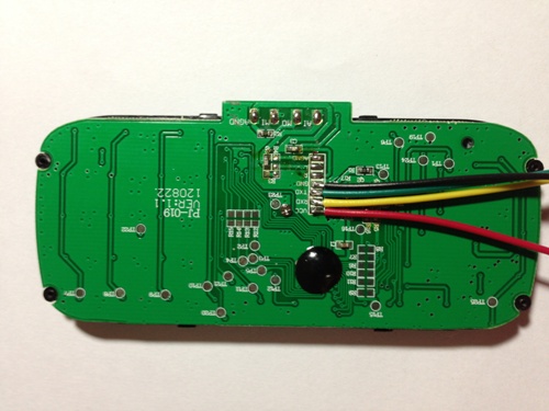
xbox360 chatpad clone, which doesn't work
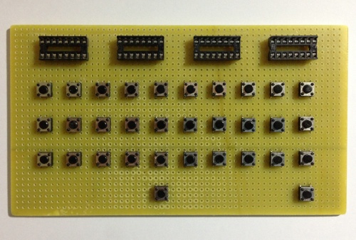
Unfinished custome made mini keypad
The keyboard has 32 keys. The IC sockets on the top are for CMOS 4021 chips, which are 8-bit parallel-in-serial-out shift registers. The shift registers will be Daisy chained. I'll place a LED next to the SHIFT key to indicate if SHIFT is switched on or off. Let's see how this turns out.
More about Daisy chain shift registers:
http://www.lucidtronix.com/tutorials/40
http://www.arduino.cc/en/Tutorial/ShiftIn
June 16, 2013
On this foggy Sunday I managed to wire the mini keypad completely up. I have also drawn a keypad mask for the top side. The mask will be transferred to a ABS sheet by the toner-transfer-method (basically just print it on a suitable piece of paper and transfer the horizontally mirrored drawing to the ABS sheet by applying heat via electric iron).
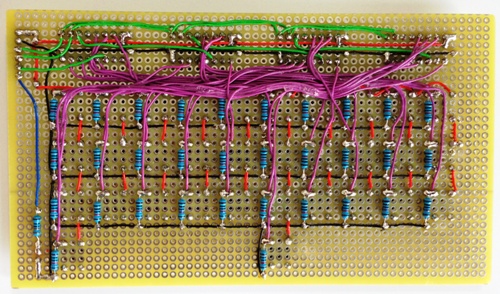
Backside of the home made mini keypad
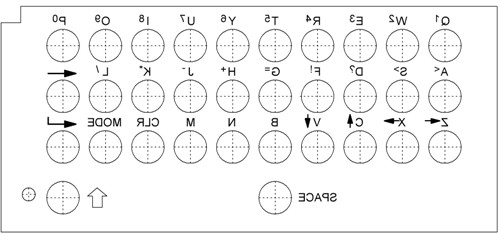
Mirrored keypad mask
Nothing for now
- Actuators / output devices: 2 DOF head, 4 DOF arm + gripper, 1 DOF hip
- Target environment: indoors


