


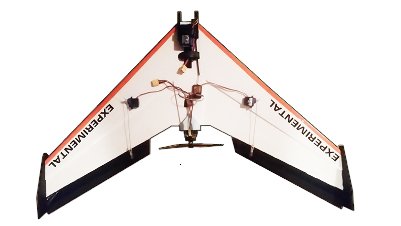
Much of the focus and attention on drones these days centers around multirotors., which have the distinct advantage of being able to hover in place and move in all directions, whereas airplanes can not. An airplane however can be considerably less expensive than a multirotor as it only needs one (rather than four or more) propulsion motors. This tutorial will explain how to make an attractive, fast, rugged, yet incredibly cheap delta wing which can be used for fun RC flying or (lightweight) autonomous drone applications.
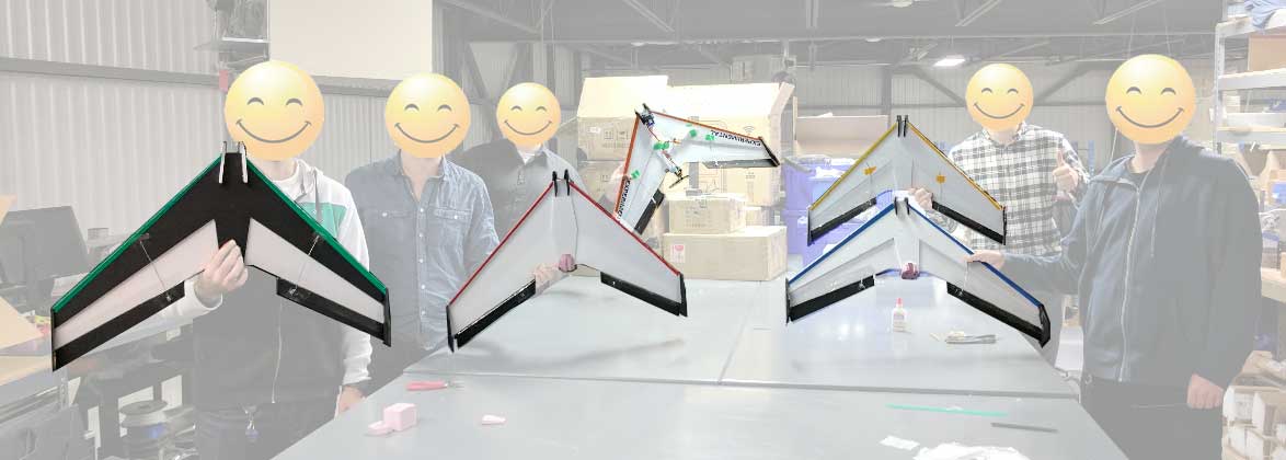
This is not a unique build - it is a result of reading through many other builder’s experiences and scratch builds, with the goal of designing and successfully flying the least expensive, fastest to build delta wing. The wing profile is based on a simplified KFm airfoil design (KFm-2). However, since the lift generated is not great, it needs to fly at fast speeds (NOT good as a trainer). Overall dimensions chosen are to try to ensure the entire center plane can be cut from one sheet of foam board. Some variations to the design are included in the files section. The following site helps with overall dimensions and calculations regarding the center of mass: http://rcwingcog.a0001.net/?i=1
The choice of materials will affect the design of the airplane, so it’s important to know what you’ll need before you start the build.
Foam Board


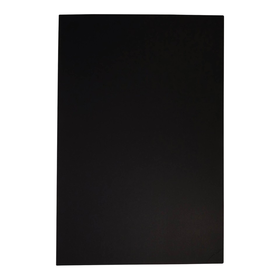

What makes this frame so cheap is the fact that it is made from 2D foam board. This board is most often found at dollar stores for around $1 to $2 each and is a general purpose material used for presentations (look in the section which contains classic Bristol / poster board). The board looks like thin foam sandwiched between paper and is around 3/16” thick (or 5mm) and very light weight. It almost always comes in white, though black can often be found too. Dimensions sold seem to be around 20” x 30”, or 800mm x 1000mm.
Given that the top and bottom are basically paper, you can change the color without any problem by whatever means you want. Your should do your best to obtain this before considering using other materials. If you can’t get the exact dimensions of the board which correspond with the design, you can either scale the design (within reason), or split it over multiple boards. One white board and one black board make for a very nice effect.
Foam board insulation


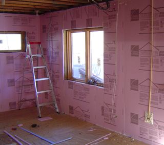

The second part of the frame is what will be used to create a motor mount. The suggested material is foam board insulation (Extruded polystyrene, or XPS), most widely used to insulate walls in houses. This is NOT to be confused with foam which has beads (Expanded polystyrene, or EPS). XPS foam is hard to compress and can be sculpted with a knife, sawed etc. while being incredibly lightweight. It’s readily available from stores which sell building supplies for homes, is incredibly inexpensive, but the size (4 feet x 8 feet for example) is far, far more than is needed. A bit of scrap XPS around 2” thick (or stacked 1”) is all you need (neighbor, scrap from a construction site etc.). If you absolutely cannot find this material, you can create a motor mount using the white foam board.
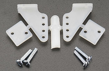
Motor supports
0.25” to 1” long (threaded) plastic standoffs and corresponding screws. These are going to be inserted (and glued) into the foam above.
Control Rods & Control Horn


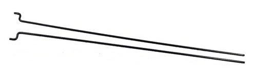
The control rods will link the horn of the servo to the control horn installed in the ailerons. The ideal control rod for this application is the metal handle which can be found on many Chinese / Asian takeout boxes. Metal coat hangers tend to be too thick and heavy for this application. A hardware store might have something like a general purpose small diameter metal rod which can be used (either shipped straight or round around a spool). Whatever you find, be sure to straighten it (using pliers, a hammer, a vise etc.).
Plastic control horns tend to be very inexpensive, but if you’re interested in creating your own, all you need is a durable, thin piece of plastic. If you can find plastic with a 90 degree bend (rectangular plastic container for example) the horn will be all that more rigid.
Motor + Propeller + ESC
The combination of motor + propeller should provide at least 0.6Kg of thrust at full throttle (the more the better). Ideally between 1500 and 2500kv and can operate using a 2S or 3S LiPo (7.4V or 11.1V)The motor should weigh ideally <30g. The (discontinued) HobbyKing Donkey ST2204 combo was the least expensive BLDC motor + ESC + connector combination we found which did not require any soldering. The wing easily had enough thrust to accelerate vertically against gravity (thrust to weight ratio of around 2:1).
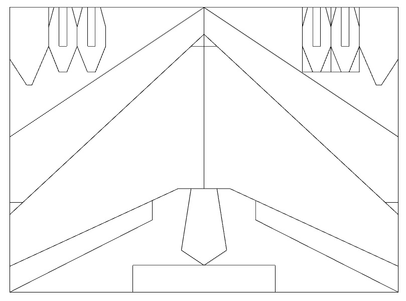
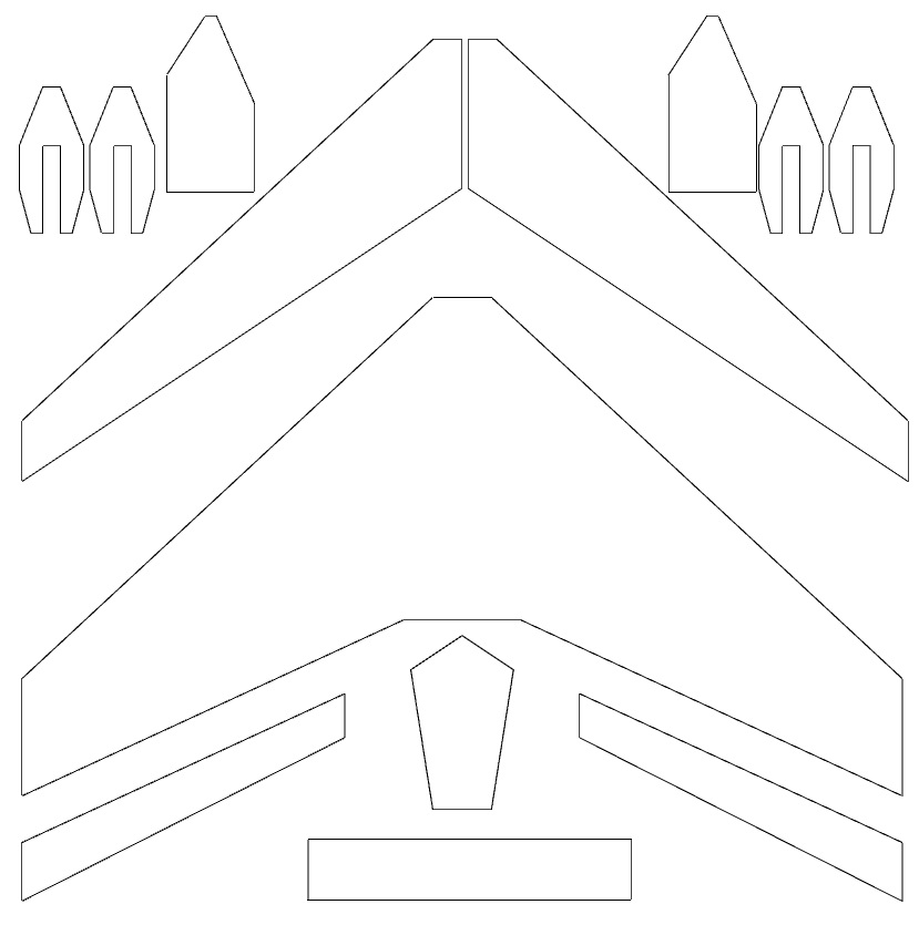
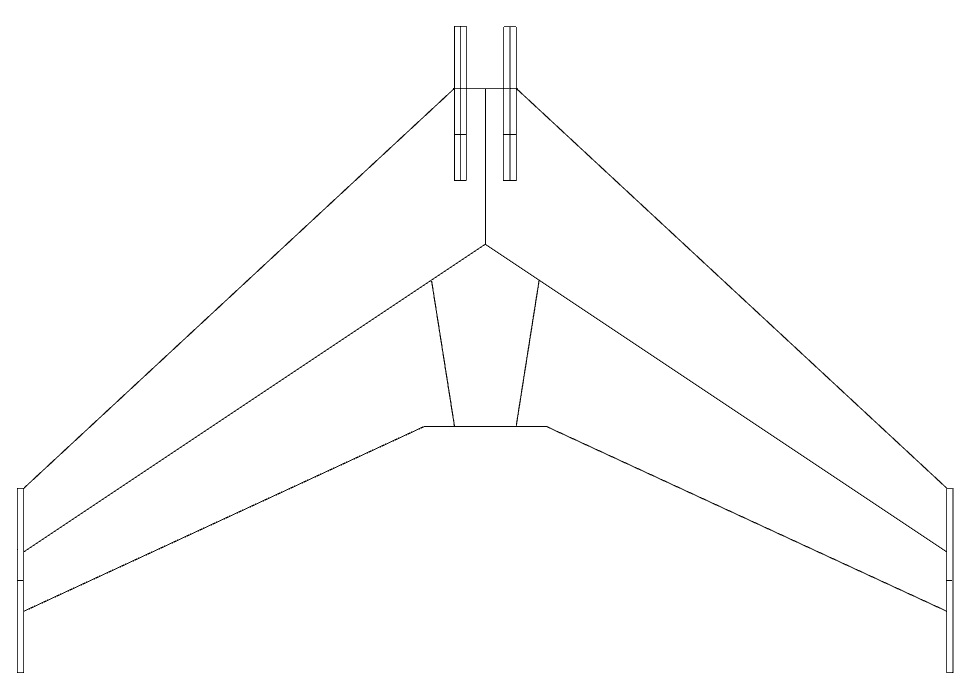
Measure twice, cut once. Despite this, you might need a few spare sheets as you become familiar with cutting the foam board in a straight line. If you’re new to this type of flying wing, trace the proposed design before altering it. Under attachments, you’ll find a design for a wing based on a 22” x 36” sheet which you can open in Google Sketchup (free software). Some of the dimensions are indicated, though you can use "Tools -> Dimensions" to check any and all dimensions. Once again, if the foam board you find is smaller, then split the design over two (or more) boards. If you're comfortable modifying the design, dimension your own custom frame using this excellent tool: http://rcwingcog.a0001.net/
In order to cut the sections out of the foam, we strongly suggest a long, straight and rigid material (which cannot be easily cut with a knife) to use as a guide (ex. a long metal ruler). Given that we made quite a few of these frames, a long “general purpose” rectangular metal plate ~1m long was purchased for $5 at a local hardware store. You will also need a new, very sharp knife (retractable $1 utility knife is perfect or an Exacto knife).
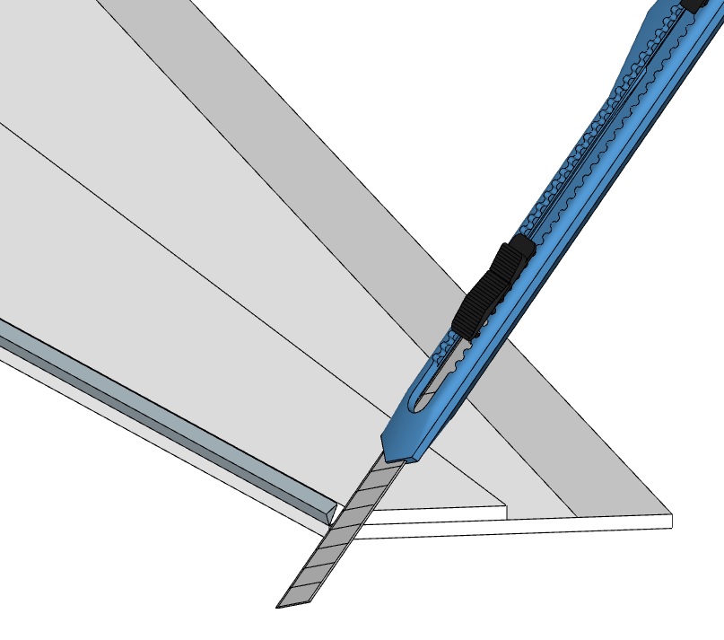
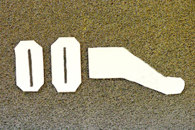
The top board of each leading edge needs to be trimmed into order to make the profile. One edge of the surface is placed against the straight edge, and the knife is used to slice at a 45 degree angle. This is most easily done by tracing a line on the top of the wing which is the same thickness as once piece of the foam (normally 3/16” or 5mm). The same needs to be done to the lower edge of each flap, as shown in the image below.
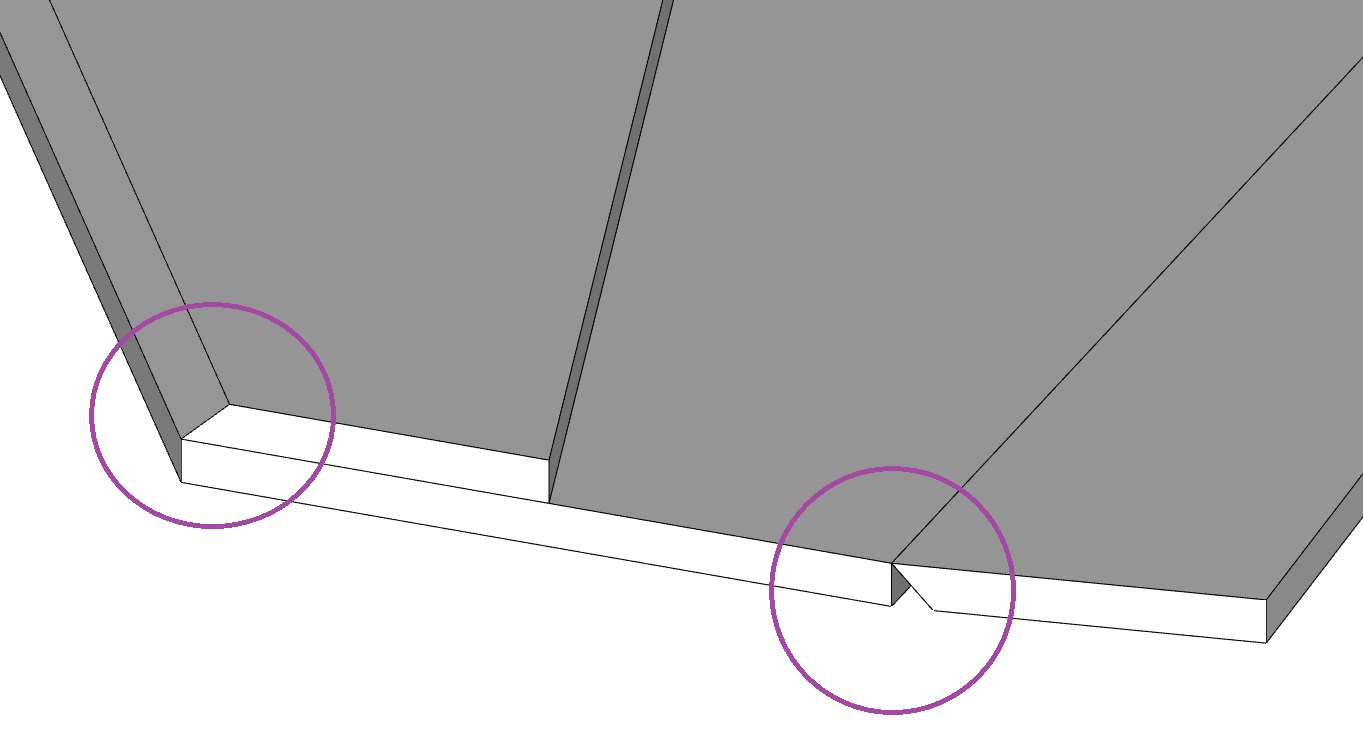
Note that the ends of the ailerons need to be trimmed to allow for full motion about the hinge, as shown in the image below:
Use normal white glue (ex Elmer’s) and spread the glue over the entire surface to be glued using a flat object like a popsicle stick, taking care to use only a minimum of glue and wiping away the excess. If you want to prevent warping, glue one section at a time and lay the parts being glued between two very flat objects, like a table and a large, heavy book. The ailerons are installed later.
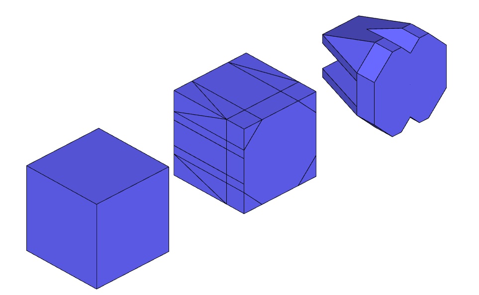
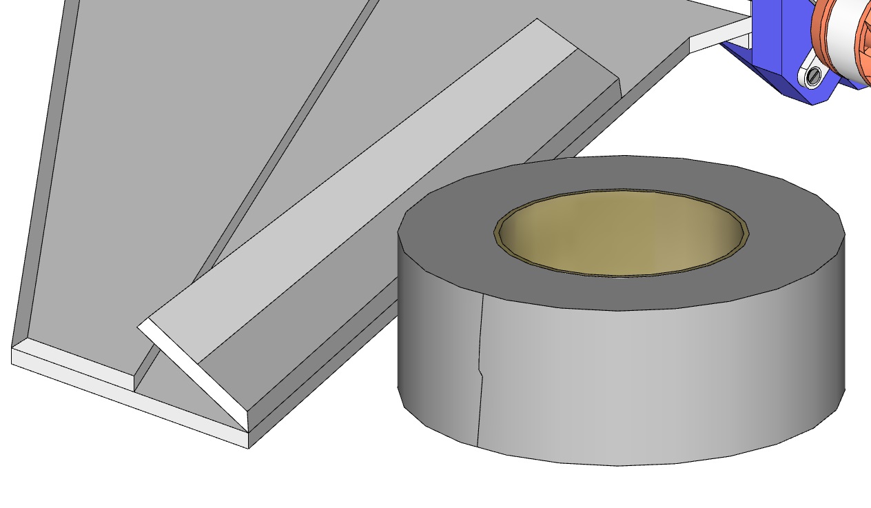
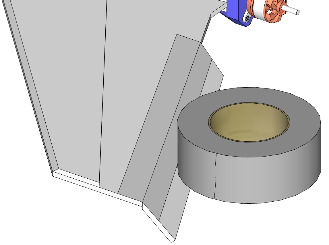
Foam board is incredibly easy to cut using a utility knife, so be careful not to cut yourself in the process. To sculpt the board nicely, use a ruler and trace a 2” cube (which is all you need) and cut it out. Next, we need to make it aerodynamic, but at the same time, have the surface needed to insert the motor mount later. Trace the profile (it does not need to be exactly as shown in the sample, though the sample works quite well), and remove each section by extending the knife as far as possible and slicing through the foam.
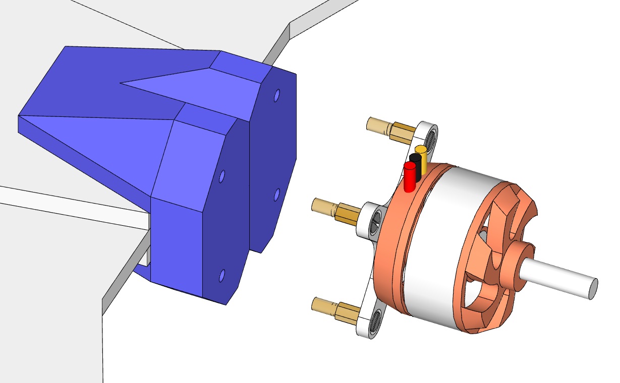
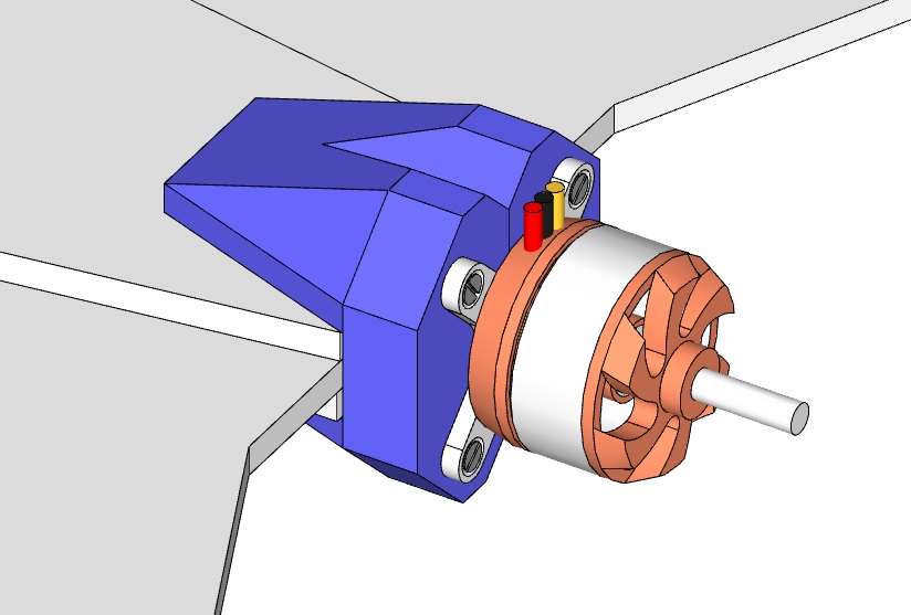
The next step requires you to already have the motor, motor mount, standoffs and screws. Connect the motor to the motor mount, then the standoffs and screws to the motor mount. You need to pierce four mating holes in the foam which fit the standoffs. Take special care with this step since the motor needs to be mounted on-axis, or else the wing won’t fly straight. We would propose using a small drill to pierce the initial holes, then move on to larger bits, taking care not to snag the foam and tear it apart. Feel free to experiment with creating proper holes using scrap foam before doing it with the sculpted foam mount.
Press the motor + mount + standoff assembly into the holes in the mount and check alignment, and then test fit this new assembly on the wing itself. “Close enough” will create issues in flight, so try to be as straight as possible along the center of the wing, and try to ensure the motor is as straight as possible. Once ready, glue the foam to the wing using white glue, then add glue within the holes in the foam mount and press the standoffs inside and let the glue set.
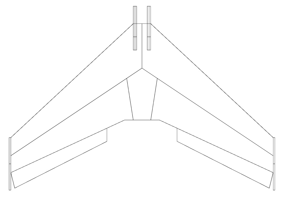
Using normal transparent packing tape at least 1” wide, flip the flap on top of the wing and tape (as shown). Rotate the flap as far as it will go downwards, and add tape to the top, creating a lightweight hinge. The images are shown without the winglets. Note that you need to have trimmed the ends of the ailerons at this stage.
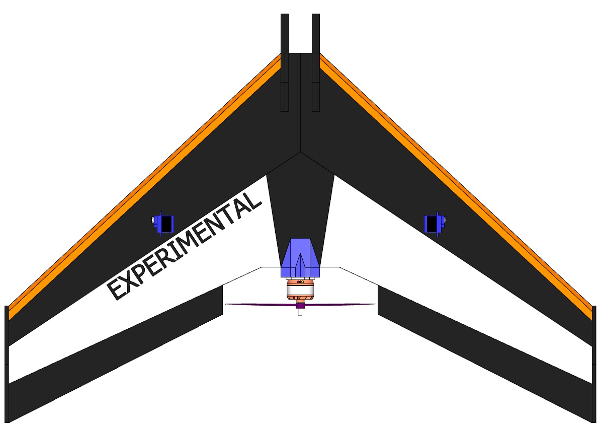
Draw / add the following design on the bottom of the drone where the center of mass should be according to the site http://rcwingcog.a0001.net/. When all items have been installed on the frame (servos, motor, receiver etc.) the airplane should balance on this point and the nose should not dip nor fall. The easiest way to adjust the center of mass is to adjust the position of the battery. Suggested positions for each component will be explained later.

This step is entirely optional.
The foam board on its own is actually incredibly rugged and the front bumpers take the shock of an impact incredibly well. During flights, we’ve nosedived from around 150 feet straight into the asphalt of a parking lot, and aside from a bit of flex / compression of the bumpers, nothing was broken and the plane was in the air again within seconds.
If you want to ruggedize the frame, consider using the same clear packing tape to wrap the leading edge of each wing. We used a thin piece of colored vinyl (with adhesive back) instead of tape. If weight is a concern, and you still want added rigidity, then you might consider a separate frame where the paper on either side of the foam board is removed (manually), and replaced it with tape.
One popular option is to include a reinforcement “beam” (thin metal rod for example) running the width of the wing. This adds quite a lot of rigidity, without adding much weight. This having been said, if you are able to fit the entire wing within the foam board, a reinforcement beam is not really necessary
The 9g servos can be glued roughly as in the image below, and should be symmetric. Note that the horns will need to be removed, the servos centered, and then replaced vertically.
Straighten the metal handle from the takeout food packaging and then cut it into two pieces. Using needle nose pliers (or normal pliers) create a flat s-bend as shown. The opposite end of the rod may or may not need to be bent depending on the control horn you select or build.
Next, two pivots ("control horns") needs to be made or purchased. There are many designs on Thingiverse which can be 3D printed, and you can use a flat piece of plastic and scissors to create your own, ensuring it is rigid and can remain vertical. The foam is not an ideal candidate for this part, and in the main photo, a pack of 10 control horns was purchased online for roughly $2. However you buy or create this part, check that it remains vertical, well affixed to the aileron and is rigid. It can be installed parallel to the servo, around 1.5 to 2" from the inner edge of each aileron.


Placement of the control horns:
Three (preferably four or more) channel RC transmitter and receiver. Note that the RC receiver should be as small and lightweight as possible. In some cases, it might even be preferable to remove the plastic case and instead enclose it in large shrink wrap. Keep in mind that your transmitter needs to be set correctly - check that the throttle (normally the left joystick) works as it should, and the right joystick controls up and down and roll left and roll right. Be sure to adjust the trim to ensure when the joysticks are centered, the ailerons are centered and the plane will fly straight.
You will need two standard 9g RC servo motors (~$3 each), and, depending on how far away you place them, might need a pair of servo extension cables. Normally RC servos include at least 6" of wire, which is sufficient.
Assuming you chose a motor + ESC combo which has a BEC (battery Elimination Circuit), you can get away with using one main battery, and the BEC will power the receiver and the servos. If it can provide sufficient current, it will also be used to power the flight controller.
As for the battery pack, verify the motor's nominal operating voltage which likely corresponds to a 2S or 3S battery (7.4V ot 11.1V). The pack cannot be too large or heavy, so ~1400mAh to 2000mAh tends to be sufficient. Keep in mind the entire airplane WITH electronics and battery needs to weigh less than 350g in order to get a nice ~two to one thrust to weight ratio.
Before adding a flight controller, learn how to fly this airplane and be comfortable when encountering unknown situations.
{Coming Soon}