


HMOD-1
I am working since beginning of this year on a new humanoid robot to continue my AI experiments.The ability of machine learning will be given by algorithms including variable structure stochastic learning automaton and linear regression (least squares - first order polynomial).
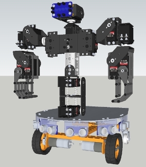
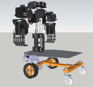
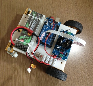
As I have more interests in creating a complex behaviour of the robot instead of complex movements, I am just using a simple 2WD platform to move the robot from point A to point B. By creating several decks on the 2 WD platform, there is enough space to assemble all the hardware and electronics.
As I moved beginning of this year to a new city, I have no workshop available anymore; I just brought some basic tools with me, so I wanted to resort as much as possible on purchasable parts. The rest is 3-D-printed, CNC-machined or laser-cut by a machine shop, which is just one floor beneath my company office.
The 2WD platform is from Makeblock, the upper body a modified version of the Johnny 5 torso from Lynxmotion. I have canceled the base rotate turntable and changed the original 1 DOF head with ultrasonic sensor to a 2 DOF head with IR compound eye. I have changed the claws in the original design as well by grippers.
Following input/output devices are planned in the moment or already implemented:
- 6 HC-SR04 ultrasonic sensors
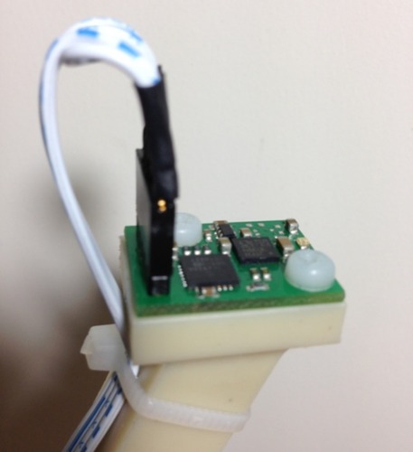
- Devantech CMPS 10 compass module (employing a 3-axis magnetometer and a 3-axis accelerometer)
- IR Compound eye
- Force sensors mounted on the inner surface of the grippers
- Costum made speech recognition board based on the HM2007 chip (I love the fact that this chip works with perceptrons)
- Parallax Emic 2 Text-to-Speech Module for TTS
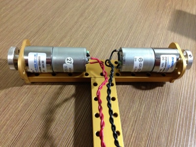
- 2 geared motors for propulsion
- 12 DOF torso, servos controlled by an Adafruit16-Channel Servo Driver
After I had written the basic algorithms for machine learning, I started to design the robot, based on the parts I wanted to use.
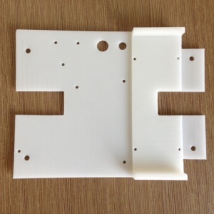
The supplied geared motors of the Makeblock platform were not suitable for my project (turning too fast, too less torque, rated voltage 6 V instead of 12 V, drawing too much current). I replaced them by 12 V-types with a gear ratio of 1:184 instead of 1:75. The material of the first deck is nylon and CNC-machined. It holds mainly the Li-Po battery, the microcontroller board and the on a L298N (multiwatt version) based motor controller.
The second deck is machined from 1.5 mm aluminium sheet and holds the ultrasonic rangers and the main torso.
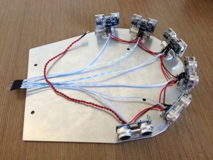
The six ultrasonic rangers are arranged in an arc of 180 degrees. The holders are made from aluminium and have a kind of hinge to adjust the angle. I found them on taobao. The obstacle avoidance will be done by the so called bubble rebound algorithm.
So far I have only programmed some very basic movements (see video), mainly to evaluate where I should assemble the compass module, avoiding electromagnetic interferences caused by the servo motors or moving ferrous metal parts.
Update March 28, 2013
Compass module holder finished. The holder is machined out of one piece nylon, rock solid but light weighted. The PCB was mounted on the holder via M3 nylon screws after I tapped the upper plate accodingly. The compass module holder will be mounted on the rear of the robot. They guy in the machining workshop misunderstood my comment in the drawing "part no. 3" and machined 3 pieces instead of one...Doh.
I also worked on the software side, the IR compound eye head is now tracking objects and the basic code for the IK of both arms is written. I furthermore attached a paper (Supervised machine learning) in which I show the derivation of one of the simplest formula of supervised machine learning - linear regression (least squares - first order polynomial). 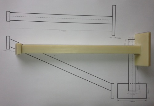
Interacts with its environment and human beings and learns from them
- Actuators / output devices: 2 geared motors, 12 Servos, loudspeaker
- Control method: autonomous
- CPU: Arduino Mega
- Power source: 11.1 V / 3300 mAh Li-Po battery
- Programming language: Arduino C
- Sensors / input devices: microphone, IR Compound Eye, HC-SR04, tilt compensated magnetic compass, force sensor
- Target environment: indoors