


More vids can be found via my Youtube channel: Razorgon Youtube
Lets start!
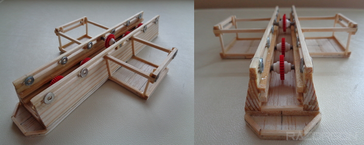
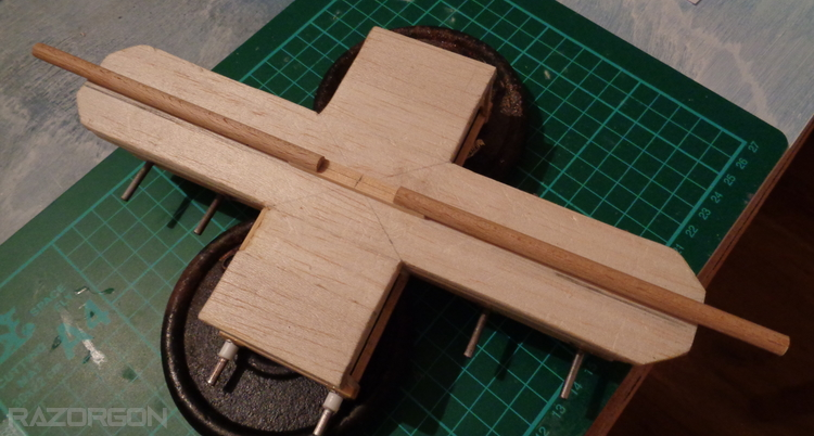
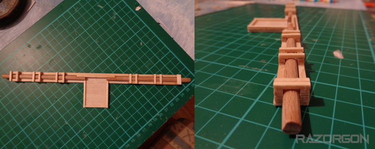
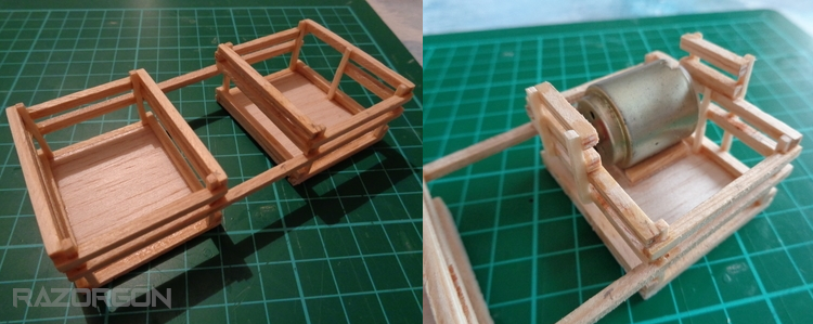
Construction of the main body that will house the gearing system and support the drive joints.
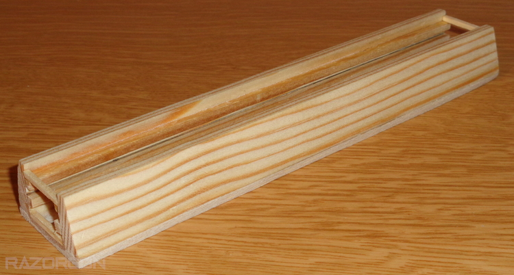
Ridges made to hold and support the gearing system, lower and upper level
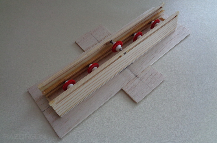
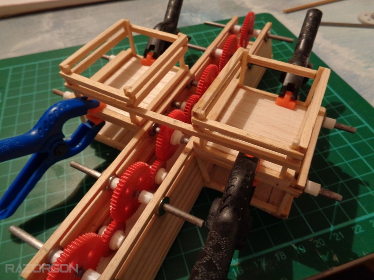
Adding The Lower Gears
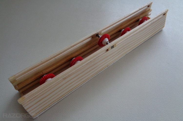
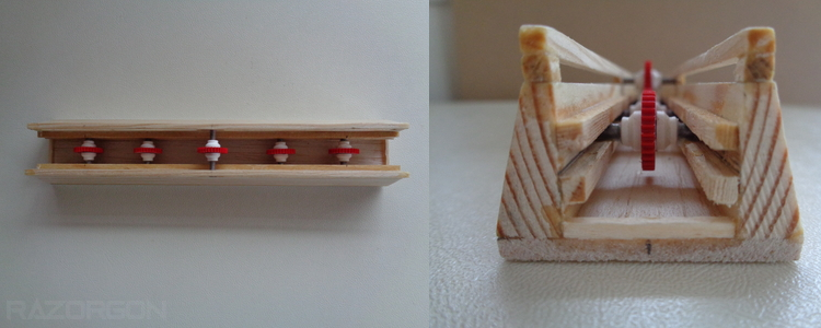
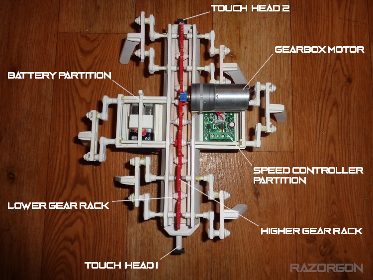
The lower gear rack is made up of small gears run across the lower rail and put in place. The central drive gear is also added.
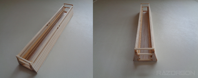
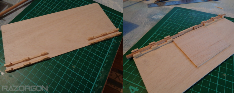
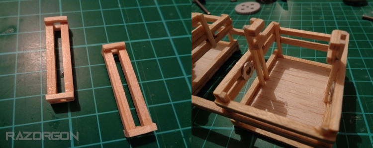
Toby has 2 central partitions for components, i wanted to have the size as small as possible so there wouldent be too much weight. As well as that i did not want to go over or under with the mid legs, so by expanding the mid section the legs could all be on the same level. Who wants to do more work on the mid section? :D
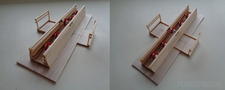
With the partitions added and glued in, the excess wood was cut away to leave the base of the robot.
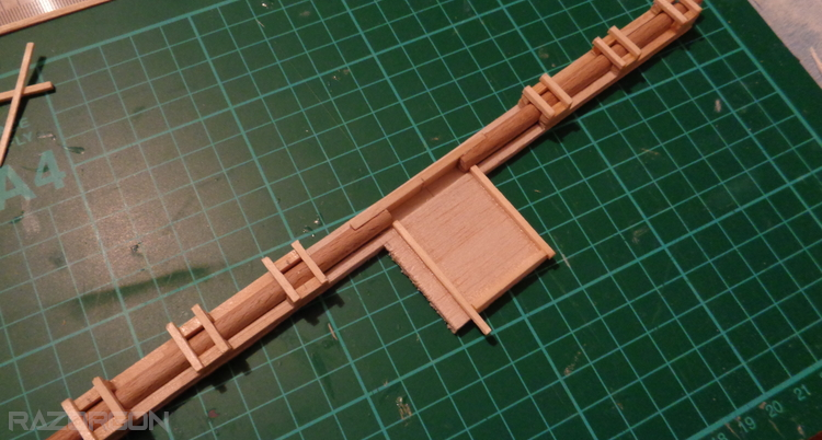
I added 2 pin points on each end of the body which is used to hold the robot when moving or carrying it, this was the main housing for the touch sensors at the start but was changed later on due to the sensor being under the body.
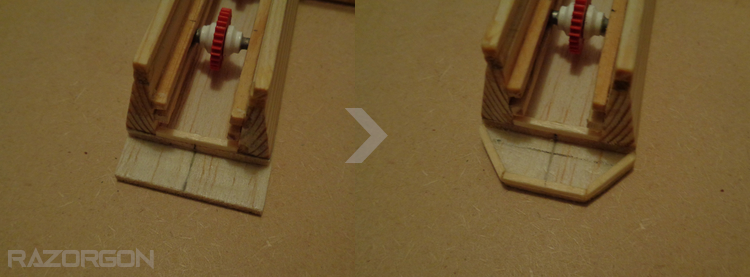
Side, front and back partitions complete, washers were added to help support and align the drive and larger gears. The washers were removed later on due to allignment problems though, the joys or gears and being a noob >.<
With the main body and gear alignment complete it was time to roll up the sleeves and tackle the crank joints! Do i need a 3d printer?? -.-
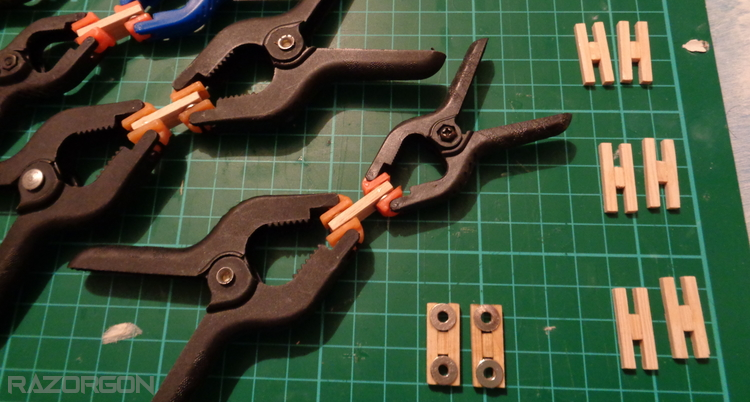
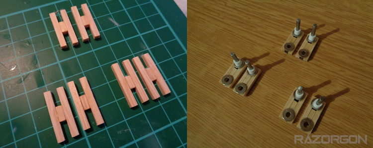
Each crank is sanded and double glued reinforced, over done it here but i dont want any joint coming lose or breaking when finished!
Upper gears Added
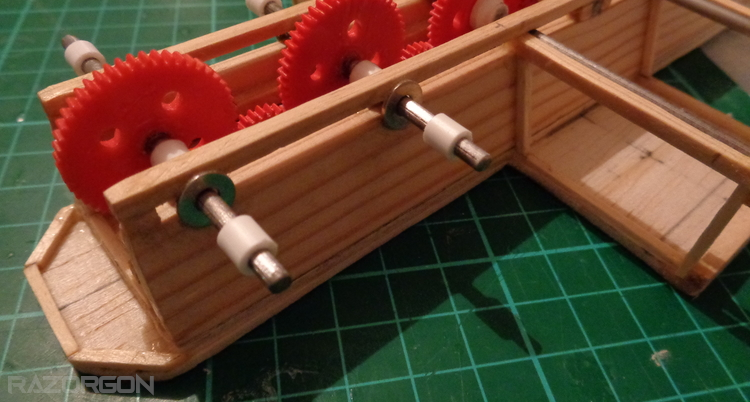
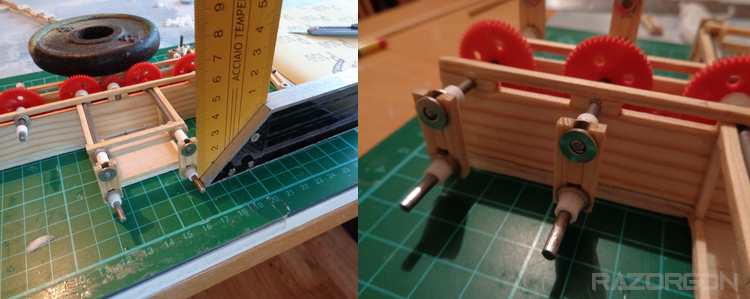
With the large gears and drive shafts added, the cranks were put in place and aligned, this is some pretty stone age alignment methods going on here but hay! i hobby out of my kitchen atm! :D
Making the legs were a challenge! i must have broke 1 or 2 legs about 4 times by just human error and misplacing my hands, easy to fix thankfully! :D
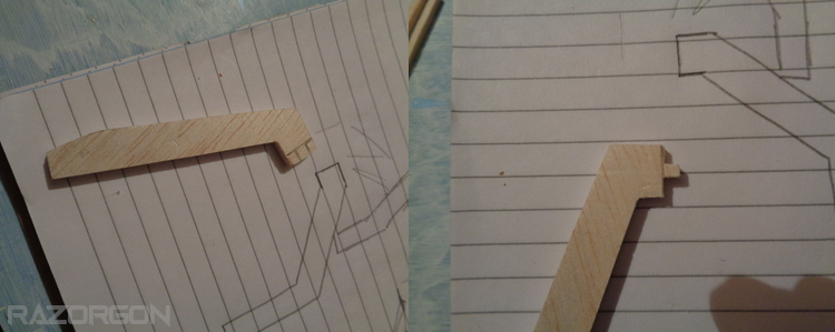
The cut outs were done on paper and traced over, i made a center connector at the mid top so that each leg with snogly fit to the joint plate.
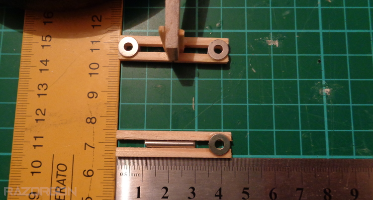
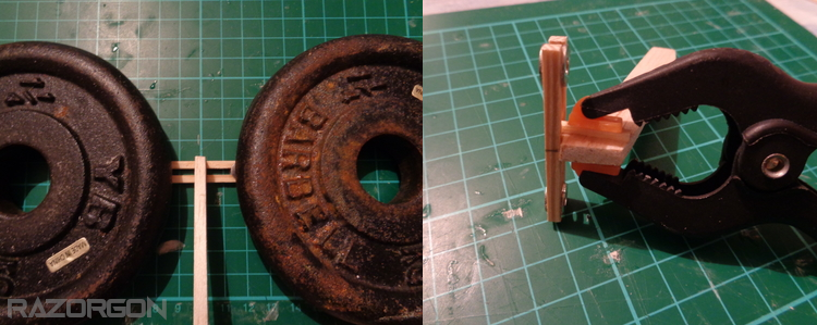
The leg plates are made up of 2 straights held together by washers each side, weight plates were left on top of them to give a stronger bond when glued. Ridges (matchsticks) were added to each side at the top of each leg to better secure the plate and leg.
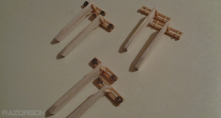
The 4 legs with washers are the side legs, the other 2 are the mid legs.a small support beam (matchstick) was added for each leg to help distribute weight.
I tend to fall under heavy influence of *why buy when u can build* mentality, while this is true in many aspects, other factors can complicate this...such as time or money. I wanted this touch sensor to be digital more so, with the idea of using 2 relay switches, but i could not get my hands on them locally and buying online means waiting, not one for waiting! ^^ so i decided to build, live and learn.
Setting out of the rod which will be used as the overall direction change switch.
Cutting out the center point which will hold the switch, support straights added, sanded, glued and ready!
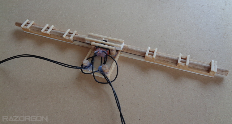
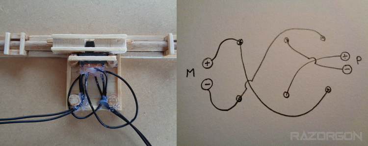
Switch installed and wired up, this was the second switch i used as the first i glued the internals by mistake :D
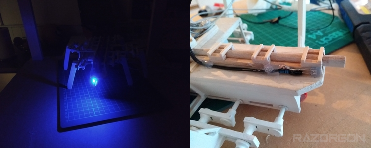
L.E.D's were added to each side, tryed yellow and white but blue was just perfect! It gave the robot that little bit of character i wanted. The lights were wired wrong though, they were suppose to point and light up the same direction as the robot was moving. I could have re wired it all again but the mistake grew on me and i decided to leave it be.
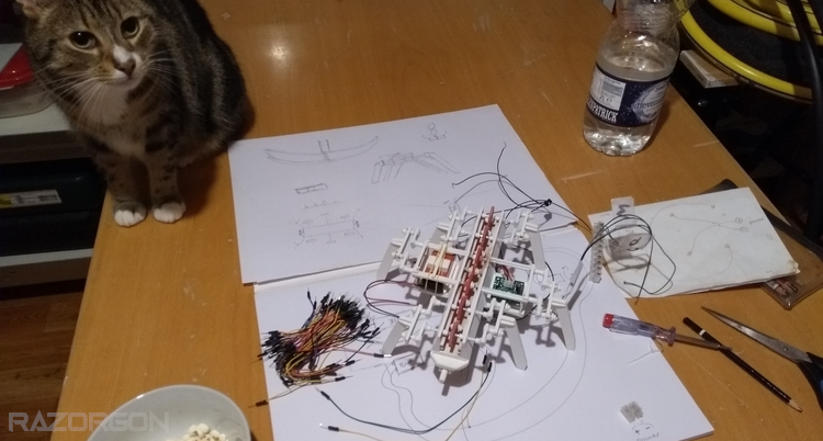
A late night of wiring and popcorn, with the company of one of my cats (Skipper)
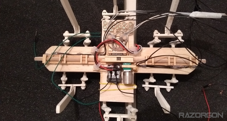
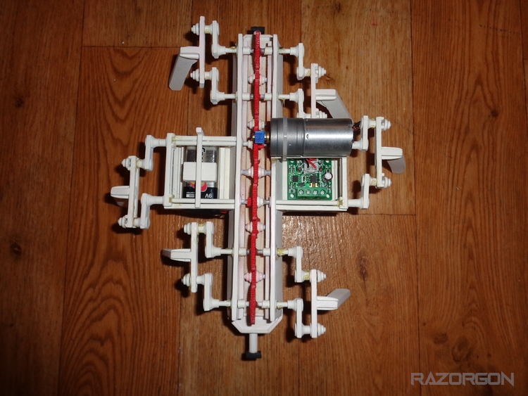
The speed controller was abandoned due to the robot going at the right speed, i decided there was no point in using it, of course this was decided once i had glued it in so well not even the terminator could nodge it without destroying the whole thing.
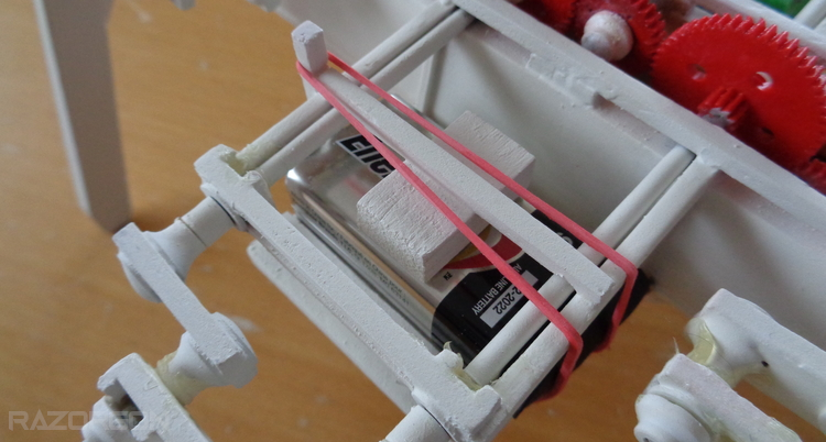
Originally the battery was gonna be 1-2 6v camera batteries, but the 9v was the perfect size and worked well with what was needed. So i went with the 9v, it sits in snug and is held by an elastic band that wraps around from the top to bottom.
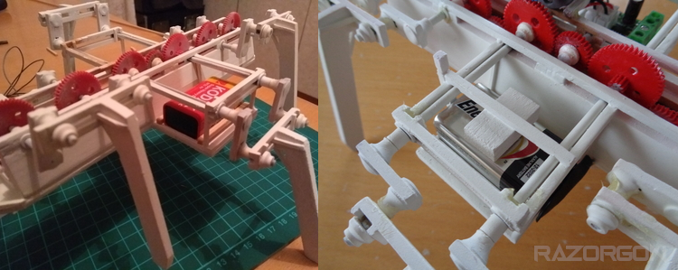
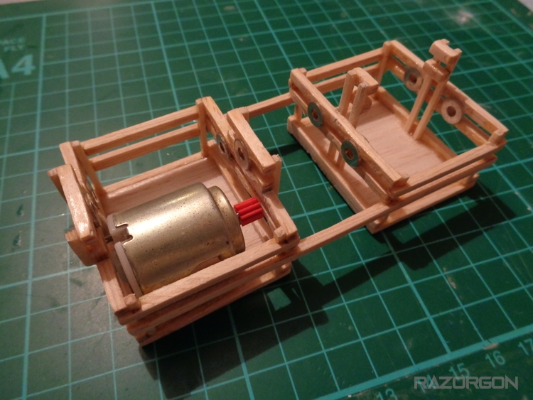
The first gearbox idea was my own and i built it to a standard of it working, however the alignment was not perfect and through friction made movement slumpy and struggle-som! So i decided to scrap it and buy a good motor with a built in gearbox. Add a speed controller and done! Once all was installed though the speed controller was not needed as the overall speed was just right. Always learning :D
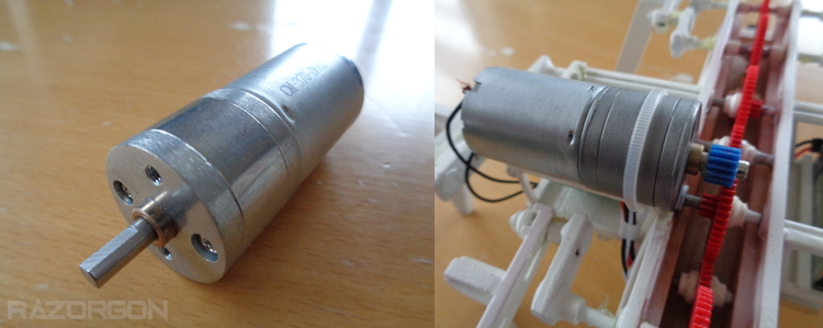
Original Gearbox Idea
Fist idea for the drive that was later shelved due to in-perfections :D
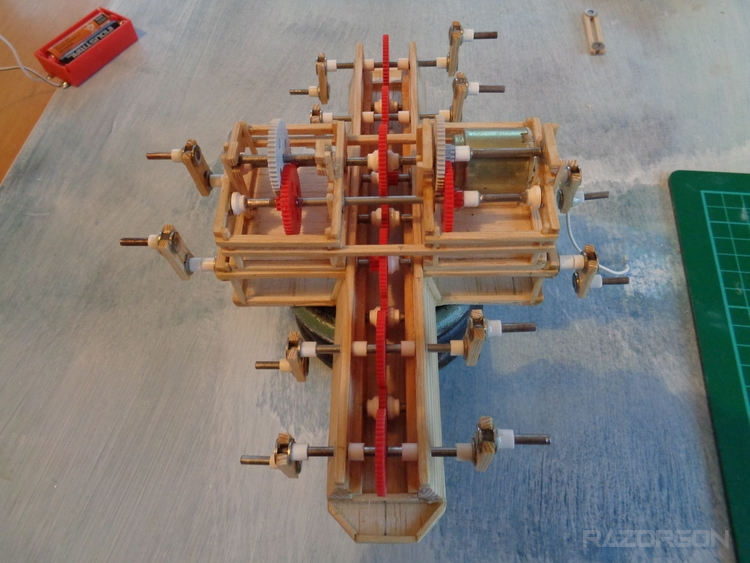
It is a shame it dident work, it was the biggest gearbox i ever made, i learnt an awful lot and enjoyed making it, dident walk away empty handed! ;)
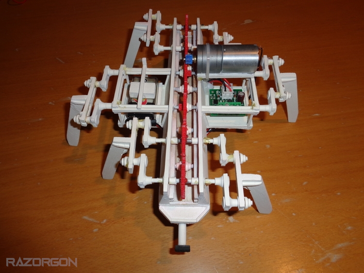
Custom Gearbox Breakdown
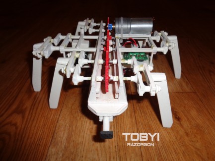
Some finished pics of Toby1.
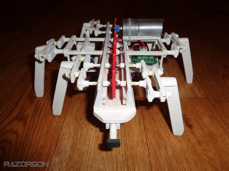
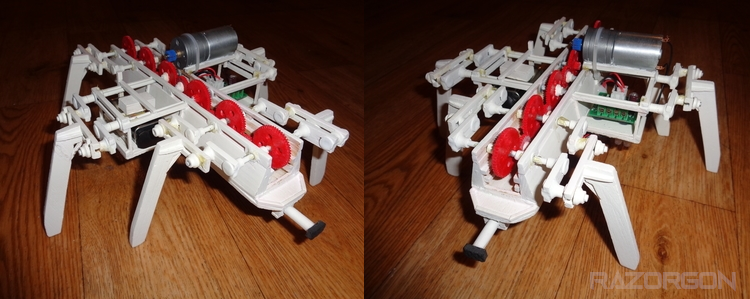
Making this robot was so much fun, although it came with many hardships, a lot were brought on by lack of planning better, something i will work on for future projects!
I appreciate and welcome any feedback, comments and questions if any.
Thanks for the views! Best regards to everyone!