


Head, The Big Headed Robot
Meet Head, the big headed robot. Head's life is really simple being just joy and play. Well, for now at least. That may change in (near) future if I manage to get his friend, Hammer, ready and running. But that will be another story.
As a robot Head is pretty much a simple object avoider. Head's eyes are SRF05 ultrasonic range finder. SRF05 is placed quite close to the top of Head's head so he also has a front bumper for obstacles that are too low for SRF05 to catch. There's also some RGB leds inside the head to give his eyes some color and to be used as signal lights when turning. Those small spots on the top edge of the head are infrared leds to help Hammer find Head (when I get Hammer finished). Head moves with two Solarbotics GM3 motors and he gets his power from four AA NiMH cells. Head has Picaxe 28x1 on Picaxe 28 project board for brains. Front bumper is done with micro switches.
A few words and pictures about construction
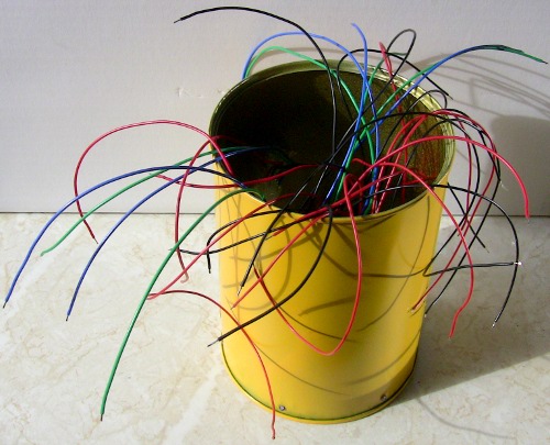
It all began with a hunt for suitable head. I was already thinking about using a tin can as a head when I was visiting my parents and spotted this baby:
Looks like a perfect robot head doesn't it
After some drilling, dremeling and sanding that can of Viennese Wafers turned to this:
Spooky eyes, huh
Head won't do much without a body so let's have a look at the chassis. Chassis started out as a battery holder, motors and a ping pong ball for a caster. Nothing fancy but it works and it's easy to make. Just glue on motors with hot glue and that's it.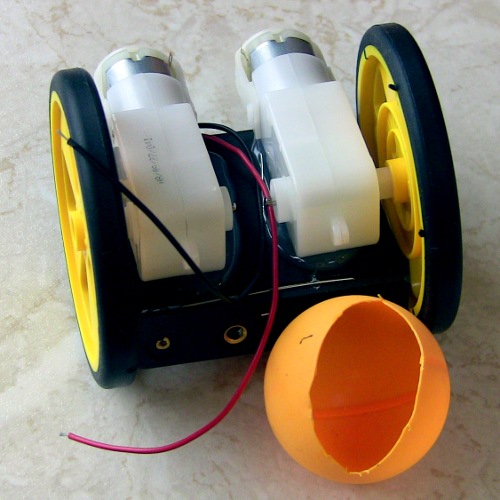
Motors glued on and caster waiting for its turn
Then I needed something to put the head onto. I built a platform on top of the battery holder and motors and then placed a "mast" for servo. The "mast" and servo go inside the head. This way I could put the servo horn to the bottom (or top, depends which way you look at it :-) of the tin can. I was also hoping that attaching the servo this way would cause less strain on servo's attachment and shaft than if the whole head would be on top of the servo. I tried a micro servo first but the head seemed to be too much for it to handle so it was replaced by a standard servo.
Servo platform and "mast" are made of paint stirrers, hot glue and plumber's tape (surprise!) and this is how it looks like:

Front view

Back view
In those pictures above there are already nice green bumpers in place. As you can see they are made of plumber's tape and just painted with green spray paint. I don't have a heavy duty soldering iron so I used kitchen stove to heat that plumber's tape. Don't try this at home kids!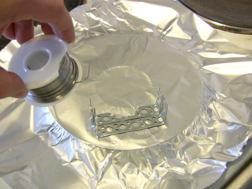
There's some tin foil to protect the stove. I didn't want solder all over it.
Used some wire to keep pieces in place. First solder joint already done.

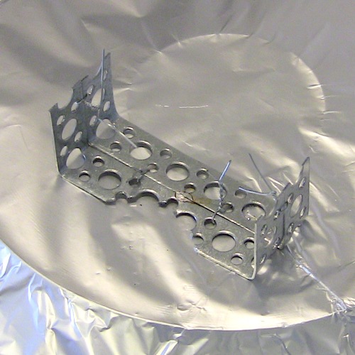
Ready for painting.

Front bumper soldered together.
That front bumper came out a little bit too massive so I cut it in half before painting and attaching it. The front bumper is glued to two micro switches and there's also "suspension mechanism" giving it some support. The suspension mechanism is a left over from my LadyBugBot clone and you can find some more details about it here (look for "Nose suspension system"). I removed the spring from the suspension mechanism because it was making the bumper too stiff. The suspension mechanism is attached on a piece of polymorph with a screw and it can move left and right a little bit. This helps the bumper work in situations where an obstacle only hits it close to left or right edge.
Front close-up. You can see the attachment screw lurking behind the servo cable.
Here's a couple of close-ups of the rear too.
Rear close-up 1. Notice how nicely Picaxe Project Board's programming jack fits to plumber's tape's hole.

Rear close-up 2. There's a homemade "IC socket" made of polymorph and female pin headers placed on some outputs.
Close-up of that homemade "IC socket". There's resistor for servo signal on output pin 1.
I connected PWM signals from port C to L293D motor driver just in case I would need them. Note: At this point I didn't remember that Picaxe has some difficulties doing servos, PWM, sounds and other timer stuff simultaneously. Because Picaxe 28 Project board's motor driver socket has enable pins directly connected supply voltage I bent enable legs of the L293D upwards so that I could connected them to PWM pins with wire. Note: If you ever try to bend IC legs like this be extra careful not to break them! (I didn't.) Unfortunately I lost all photos of the modified L293D but here's how it looks like in its socket: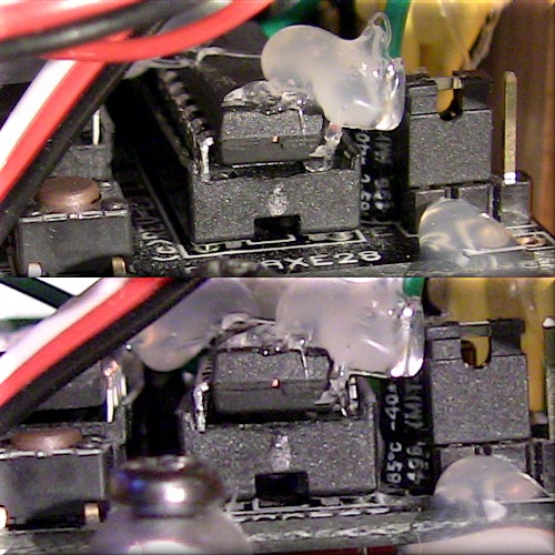
Modified L293D in its socket. Enable pins are connected to PWM pins. Some hot glue in there too to give extra support to bent legs.
Now let's have a look at that head again. SRF05 eyes have some polymorph on them too. Polymorph's job is to make eyes look nice by "diffusing" RGB leds' light.
Close-up of eyes.

Eyes inside the head. Servo horn in the picture is for micro servo that I tried first. It's now replaced with standard servo.

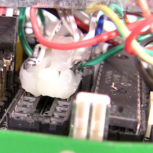
IR and RGB leds are in place.
It looks like a can of worms.
In addition to SRF05 and leds there's also a "led driver board" inside the head. The board has ULN2803 for driving those RGB leds and it had resistors for all leds. When making this board I kinda forgot that resistors have power rating too and after trying it for the first time I quickly noticed that 100mA IR led is too much for those tiny 1/4 watt resistors even though I tried two resistors in parallel. My solution to this was to make a separate "power board" for those IR leds. Because I didn't have any high power rating resistors and I don't have any electronics shop nearby I now used three resistors in parallel to distribute power. Those resistors still get warm but I don't burn my fingers on them anymore.
Led driver board (with IR led resistors still on board).

Led driver board from the solder side.

Fixing the "Hot head": Separate power board for IR leds

It's all in there.
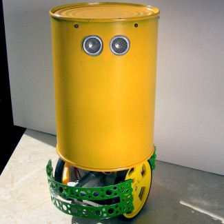
That's pretty much all there is to it unless I'm forgetting something. Here's the completed Head, the big headed robot, once again:
Does my head really look so big?
Editors note: That remote_soccer_demo_01.zip attachment is more related to this. But it contols Head's head remotely so I attached it here (beware of real ugly code).
Navigate around via ultrasound, avoid some obstacles, play Monty Python tunes
- Actuators / output devices: 2 x solarbotics GM3 motors
- CPU: Picaxe 28x1
- Power source: 4 x AA NiMH Batteries
- Programming language: Picaxe basic
- Sensors / input devices: SRF05, bumper switches
- Target environment: indoors