


HD-Bot
HD-Bot is my first intend in building robots. His name is is derived from his chassis, which is an an old hard disk case. There is no controller onboard, the motors are controlled by a comparator chip (LM393). The line sensors are build with 2 CNY70 infrared opto reflex couplers. In a future version, 2 LDRs for light detection and a collisision detector are planned. For this reason a 4x2 analogue multiplexer is also needed.
Sensors
- 2 x CNY70 as line follow sensor
- 2 x LDRs for light detection (planned)
- 2 x IS471F OPIC for collision detection (planned)
Actors
- 2 hacked Servos (continous mode, without motor drivers)
- 2 logic level FETs (IRLZ34N) as motor drivers
Control
- LM393 comparator chip
- 74LS14 Schmitt Trigger
- DIP Switches forMode select (switch left/right)
- Potentiometers for trigger value
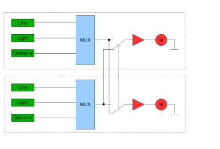
the block diagram shows the full featured version.
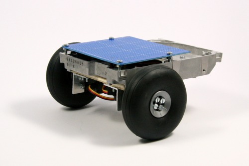
The chassis build from a hard disk case, hacked servo with attached model plane wheels.
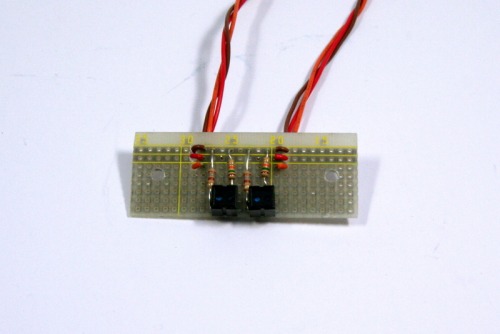
The line sensor with the CNY70 IR reflex couplers.
The motor driver board. Just 2 logic level FETs.
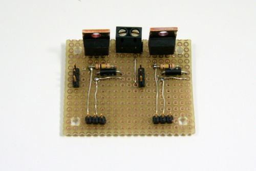
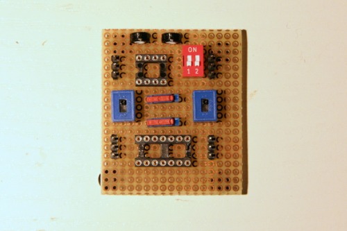
the "brain". IC socket for LM393 comparator and 74LS14 schmitt trigger and a lot of dip switches for mode select.
The following truth table helps to explain, how the logic control works:
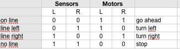
As you can see, the motor outputs needs to be inverted against the sensor inputs. The disadvantage of this simple solution is, as you can see in the video: if the robots misses the line it simple stops.
to be continued...
Follows a line without a brain
- Actuators / output devices: hacked servo motors
- Control method: autonomous
- Power source: AAs (1.2V each)
- Sensors / input devices: CNY70, line follower
- Target environment: indoor