


GUI v2
UPDATE 09/11/06
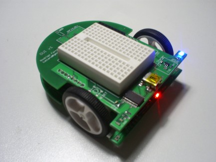
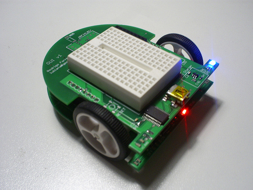
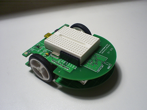
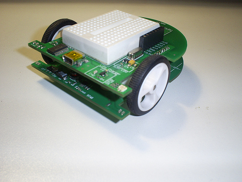
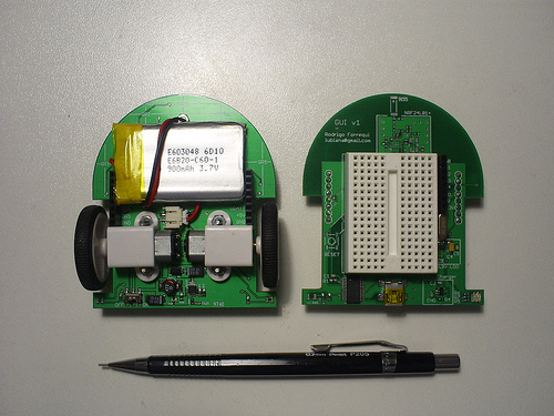
It's finished! (almost). The Motor Board PCB arrives and I've soldered all components together. The final results looks awesome to me! Most beautiful that I've planed. There's some parts that I don't solder, because I need purchase a SMD rework station (all solders on this robot are made with a ordinary solder station).
Two problems I only know after assembly:
- I've used RA4 pin of PIC18F452 for digital I/O, but unfortunately this pin is a open drain. Because that, I need to solder a pullup 10kΩ SMD resistor. Lesson: All the times, read the entire datasheet before use any device pin.
- In my Eagle motor library, I don't provide horizontal restrictions. So, a little decouple capacitor stay above the motor, touch it, and make a bad contact between boards. Solution: remove it.
Well, even with all the issues (inverted connectors, capacitors with wrong package, pin without pullups) I think the whole project was a success.
Now, the wireless part (NRF24L01+ transducer) waits to be soldered. It'll on the party next month. So, the whole project has been closed and I'll work on the software development, that I only write a very basic functions for test and maze solves.
There's a video of the test. And if someone needs more pictures or details, look at my Flickr page and my blog.
Thank's !!!
UPDATE 09/09/13
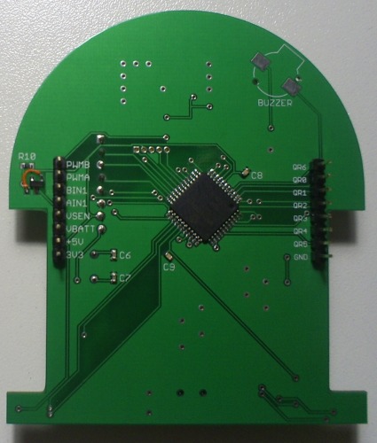
The first definitive PCB arrived from Batchpcb and are soldered!
I received the board at this weekend, it's the first definitive PCB of my GUI robot. It's your Motor Control PCB. Above are some images. Only left to solder the nRF24L01+ because I don't have a Hot Air Reflow Solder, and the Buzzer that I can't find.
Note that I've made a little mistake on p-Channel MOSFET SOT23 pinout (orange wire fix). But nothing too horrible (but in the GUI v2 design, I'll remember that...).
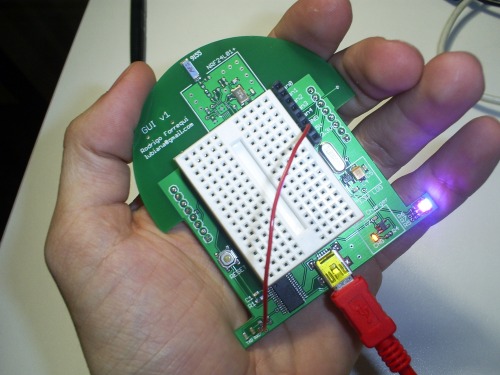
The new YouTube video contains a little test to PIC18LF452, to see if it's alive. The test was a successful.
Now, I expect that in the next week the Motor Board arrives too, so I'll complete the entire robot.
UPDATE 08/25/09
My PCBs are shipped! I'm very excitted to pick them up and solder everthing! But this update is about the schematics. I released the entire schematics of two boards and now I comment the most important parts. The full schematic are in the attachments.
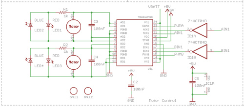
Motor Board - Motors
The Micro Gear Motors and the H-Bridge circui. To save two I/O pins on MCU, I used a 74HCT04 for drive the directions commands. I have never used other combinations (like 11 and 00) in control logic. You can see on left down two Ball Caster. I put two because I need two orientations on holes.
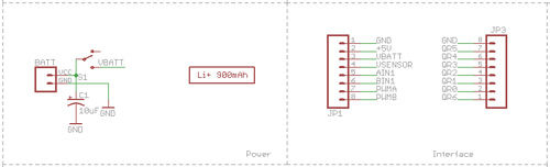
Motor Board - Battery and Interface with Controller Board
This is how the battery are attached to board. Nothing special. On the right are the female housing for up board connection. On of them is for reflectance sensors signals.
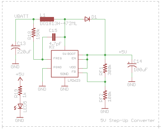
Motor Board - Step-Up Converter for 5V
The LM2623 is a great Boost converter. Is very small (LLP or Mini SO-8 package) and use very tiny inductors. The output voltage is given by RF1 and RF2 voltage divisor by RF2=RF1/[(Vout/1.24)-1]. The frequency of PFM (Pulse Frequency Modulation) is setted by R18 andmay vary with input voltage (See page 6 of datasheet). In that design the frequency stay between 500KHz and 1MHz. The input and output capacitors are Tantalum capacitors, with X5R or X7R dieletric. I spect 85% of mean efficiency (over the voltage input range and current variation).
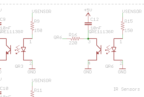
Motor Board - Reflectance Sensors
These are the QRE1113GR Reflectance sensors. I have to write their symbol and footprint, because I don't find them in any place. So, I spect that the design is correct, specially the footprint. There's a lot of stuff on this robot that I have created the Eagle library. If anyone needs, I put my personal library here.
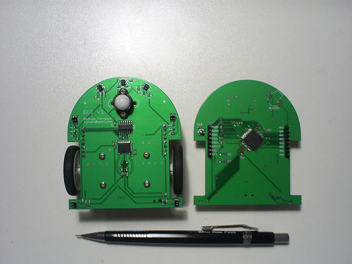
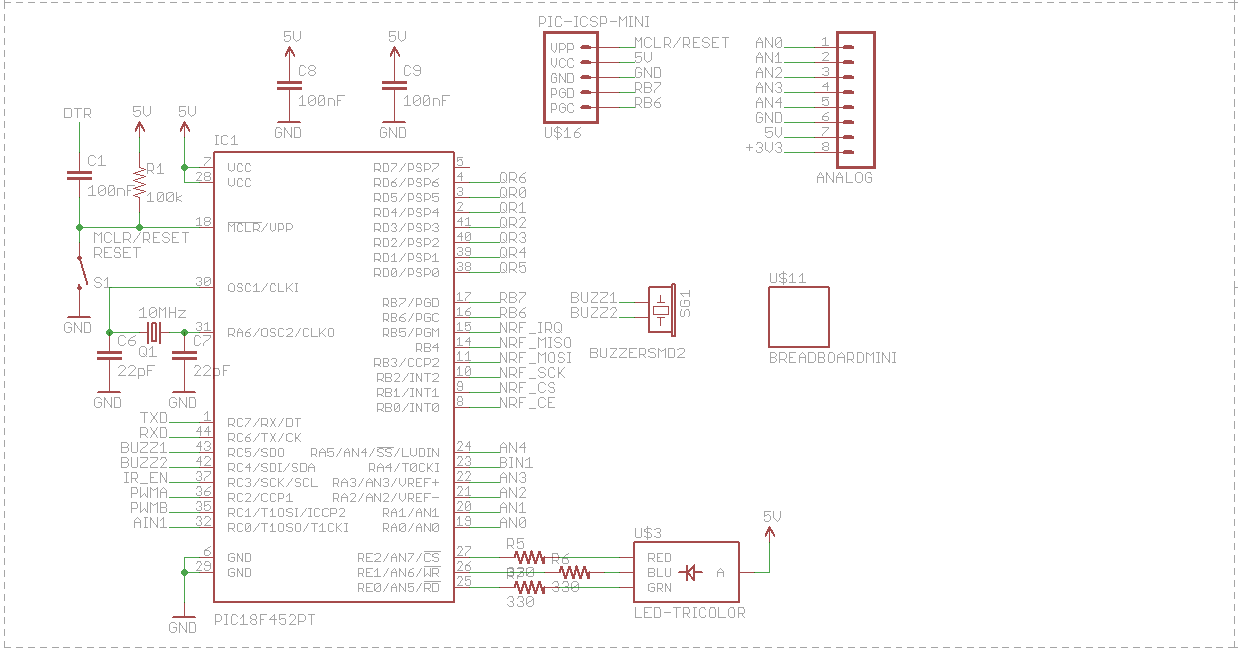
Controller Board - MCU
Nothing special on MCU. Is a PIC18F452. Detail is the Breadboard Mini, for small prototype.
Controller Board - USB Interface and Battery Charger
The Interface is given by a FD232RL, with self-power configuration. The 5V of USB don't power the robot, instead, charge the LiPo battery via MAX1555 circuit. I like MAX1811, because mre option like Low Batt indication, less charge time, but PCB space is a concern here.
After send the PCB for fabrication, I see a little mistake on this design. If you look this with Battery schematics, you see that only with the "ON/OFF" robot switch in "ON", the battery is charged. This was been corrected on next version.
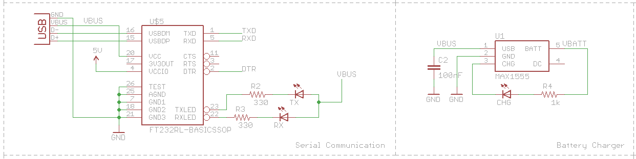
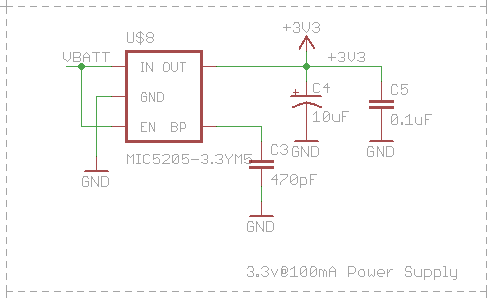
Controller Board - 3V LDO
For 3.3v devices i put a little LDO, because I don't need much power from this source.
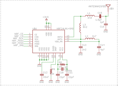
Controller Board - RF transceiver
The transceiver choosen is the nRF24L01+, from Nordic. That's design is the same of SparkFun nRF24L01+ breakout board. So, I hope that works.
Certainly this part will be the most dificult to solder, because the nRF package. I don't have a SMD rework air station. Only when I have one this part will be soldered.
Thank's.
UPDATE 08/04/2009
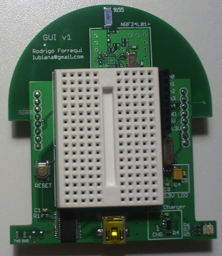
The v1 PCB design was finished!
Some things change:
- LDO (Low Drop Out) Regulator MIC5205 for 3.3v devices;
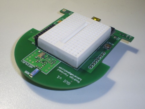
- Don't put Pin headers for stackable boards, althought I put a Mini Self-Adhesive Breadboard for small prototype (170 points in 1.8" x 1.4");
- The Nokia 3310 LCD goes off, because some dificult in it's fixation on board;
- For prototype, you have a header with 6 GPIOs (analog or digital pins) and access to +5v, +3.3v and GND;
- A Buzzer! I like things that could make some noise;
- A RGB led for general use, because I think that you need some blink LEDs to make your project a really nice project :D
The design comes with a NRF24L01+ for wireless communications. I like this little guy because your extreme very low power features (900nA in power down and 26uA in standby-I) WoW! And in most of cases I don't need full-duplex communication. With this feature, I'm stay really excitted to create a beacom frame for mutual identification between some robots, dont you?
Now that I finished the PCB design (see images bellow) I expect that in some days we have the robot mounted in the boards and look very professional.
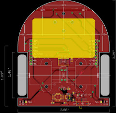
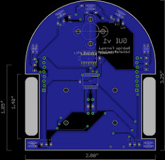
Top (red) and Bottom (blue) Layers of Controller Board (with MCU):
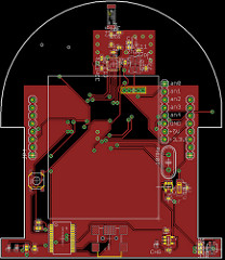
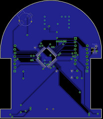
Top (red) and Bottom (blue) Layers of Motors Board (with Motors):
To view a greater image of PCBs, click on image files on begin of article (attachments)
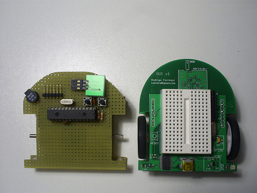
Init
GUI is a robot prototype made to be little, fast and easy to use and upgrade. In your up board (main board) it has:
- PIC MCU 18F252 at 20MHz;
- DC-DC Boost converter NCP1400-5V;
- The down board has:
- Dual motor controller TB6612FNG;
- 7 reflectance sensors QTR-1RC;
- 2 Micro Gear Motor 30:1;
- 3.7V LiPo battery.
The PIC is programmed with Tiny Bootloader, to easy program change.
Robot dimensions are 73.12[L]x77.76[W]x32[H] mm. There's a lot of space for more things, yet. More photos in my flickr page.
The prototype works great, then a definitive PCB going to be designed to increment some new feetures. This include:
- PIC MCU 18F452 TQFP, to add more I/O;
- DC-DC Step-Up converter LM2623 for 5V devices;
- DC-DC Step-Down converter (not defined yet) to 3.3V devices;
- USB Serial FTDI 232RL for serial comunication;
- LiPo Battery charge, directly from USB with MAX1555;
- Nordic NRF24L01+ for half-dupplex comunication and telemetry;
- Nokia 3310 LCD;
- Pin Headers for stackable boards (like Arduino), for add... anything!;
Navigate around, line folowing, wireless telemetry
- Actuators / output devices: 2 x 30:1 Micro Gear Motors, Buzzer, Tricolor-LED
- CPU: Microchip PIC18LF452
- Power source: 3.7V LiPo Cell
- Programming language: undefined
- Sensors / input devices: 7 reflectance sensors
- Target environment: indoor flat surfaces