I have decided to move on to other things, GPS had some serious flaws, one of which would require me to drill out all the rivets, remove his shell, and replace two of the motors (one of the orriginal motors from the drills was almost totally burnt out, was drawing an excess amount of current, and generating lots of heat and bad smells. due to poor design and planning, I would have to remove the whole shell, which I rivited together, and at that point, I am better off just making a new bot.) At some point, I will take him apart and salvage all the pieces I can. May you rest in pieces big guy, I learned a lot making you. I posted all the cover pictures, plus a couple extra ones on my blog at http://boomsandbots.blogspot.ca/2013/09/gps-from-beginning-to-end-in-pictures.html (there were a lot of them, and blogger has a slightly easier and faster picture upload process than here :) ) Last update: 9/7/13 GPS is a work in progress, and this is his build blog. I hope to have simi-regular updates on his status, as things get finished, or as I learn new things. :) scrool to the bottom for updates.
GPS's goal in life will be to navigate outdoors to GPS waypoints chosen either thru google earth, or by going to them and reading them off the screen.
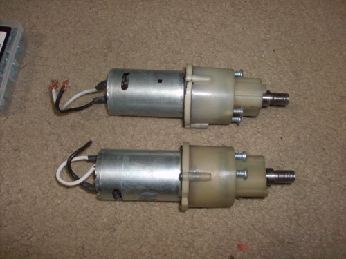
To this end, I have decided to use 4 18 volt cordless drill motors, wheels and tyres from a 1/6 scale rc truck, and a sturdy ABS frame with a sheet metal shell. pictured here are the two modified drill motors I own, I hope to go to Harbour Freight Tools and buy 2 more drills soon. I have modified the drills by removing the shell, chuck, and clutch from leaving only what you see here, the screws driven into the front of the gearboxs serve the same function as the clutch on drill function. The wheels are threadded onto the shafts and then fastened using a screw in the middle, exactly the same as the orriginal chucks.
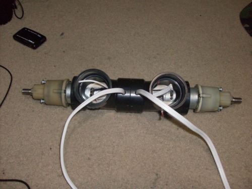
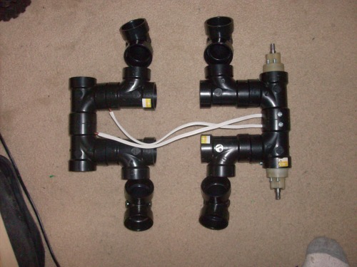
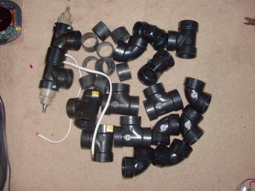
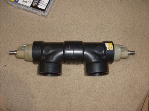
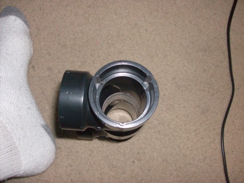
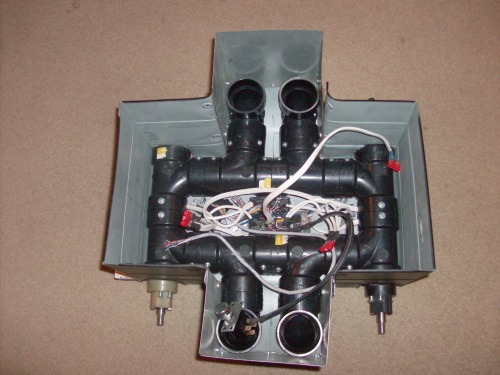
Here you see the sanitary Tees I use to house the motors in, the flanges used for connecting more pipe have 3 grooves dremeled in that corospond with the gearbox screws, this serves three functions: first, it enables the motors to be closer together, for a lesser width overall, and it locks the motor assemblys from turning. all I need are three setscrews on each side to keep the motors from pulling out of the Tees. I also have a small section of ABS to connect the Tees together. none of the pipe will be glued, just mach Drilled and screwed together.
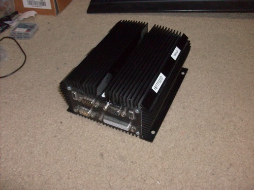
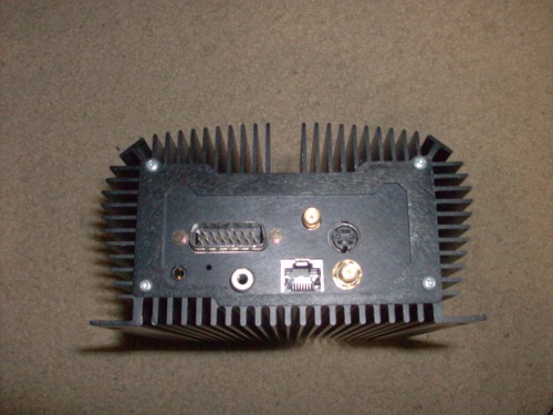
Some pictures of the custom PC that will be the brains, it is a totaly solid state device, with two 1GB compact flash cards instead of a hard drive. for I/O it has: 2 serial ports, 1 parallel port, 2 usb ports, ethernet, keyboard/mouse port, audio out, internal WiFi, internal GPS, internal mini IDE port (if I ever choose to put a hard drive or DVD drive on it). I will also be plugging a usb bluetooth dongle for connectivity. It runs off 10.8-18 volts, and has no fans, that massive heatsink lets it run in up to 60 degrees Celsius weather. If I chose not to put a hard drive in, I will probably just move windows onto a thumb drive connected thru a hub (who doesn't need more usb ports). apparently CF cards can only be written to a limited number of times, so I will only use those for ROM.
I still haven't decided what I am going to program it in, I hope to use Roborealm and a cheap webcam for vision, and just reading a little on their site, it looks like it interfaces well with VB, so possibly that. I might also give python a try, or just see if I can program the whole thing in Roborealm.
I am planning on interfacing with a SSC32 servo controler from Lynxmotion, and a picaxe of some sort over the other serial port, also possibly in the agenda, interfacing one or two lego NXT bricks over bluetooth for even more I/O possiblities.
UPDATE 10/29/12===========================================================================
I had a bit of a chance to play with my stuff over the weekend, and I found out some more stuff about my pc:
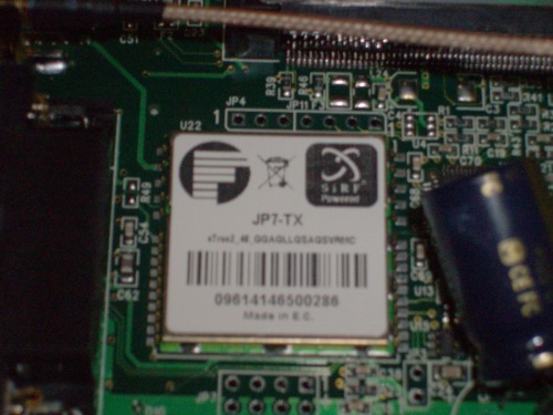
What it appears to be is a ETX motherboard mated to a custom I/O board with serial, parallel, usb etc. the gps unit is a JP7-TX as shown here: sadly, the refresh rate is only 1hz, but I am not complaining :) just mite make navigation with such a fast robot a bit of a challenge. :)
I also took apart two of my computers, here are some pics of the guts:
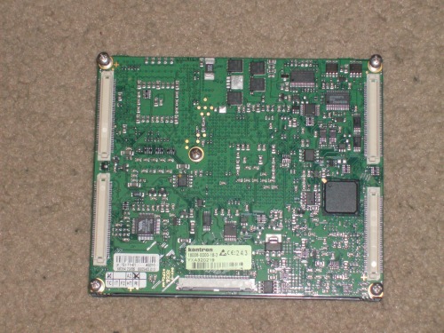
motherboard: As you can see, it was manufactured by Kontron.
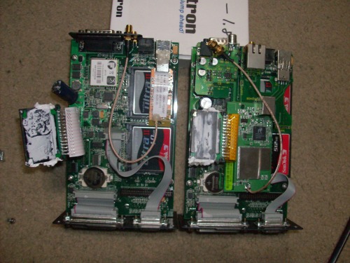
The tops of the I/O boards, notice the big capacitor on the very left of the picture, and the angle it is bent at. One leg was ripped right out of the pcb. It looks like this caused the board to be dead even before I got it.
These I/O boards just have the ETX motherboard scockets on the other side, they just clip into the scockets and are screwed on for better security. The big black thing with heat sink grese all over it attached with a ribbon cable is the power regulator board.
I have a number of motherboards from 773 mhz to 1.8 ghz that I could install, looks like 256m of ram, on all of them, I will proboably use the 1.8 ghz one. :)
The PCs I got are running the fleet manegment program they were designed for, aswell as a power monitering program that constantly checks if there is power to the on wire, and if not, shuts down after it saves everything. They are also running a funky program I havent been able to find yet, basicly what it does is takes any changes you write to the CF cards that make up for the hard disc and writes them to the ram instead, this causes the computer to completly reset everything I had done that session. This is due to the limited read/write cycles that CF cards have, unfortunately, I dont want that to happen, so I am doing everything I can to disable it. I havent figured out how yet, but the person who gave me the computers said he would help soon. I will give an update when I defeat this bit of software.
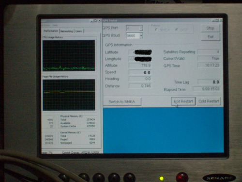
the PCs came with a little GPS tester, and I will have a screenshot up as soon as I get my Latitude and longitude blacked out. I actually posted this update with the picture intact, then realized it might not be so wise to give locations to everyone on the internet.......
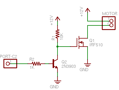
I also got time to draw up a schematic of my motor control circut: not pretty, but nobody ever accused me of being an artist :)
unfortunately it is in a pdf, so you have to look in the attachments, sorry.
I never got around to drawing up a schematic for the speed control, but it would just be the N channel MOSFETS that came with the drills, and a buffer NPN bipolar transister for driving the MOSFETS. I found this schematic on the net, and my circut will be almost the same.
I think this will make for a bombproof controler, if the 60 amp relays can stand up to the task. I think they will, seeing as the orriginal motor control swich is only rated 20 amps, and if I use the two MOSFETS in parallel they wont have a problem driving the motors. they even have little heatsinks attached already which I think will be more than enuf.
Here is a bit of progress, not much at all I must admit in the front motors: you can kinda see if you look hard, I cut a pice of 1in pvc pipe down the legnth and stuffed my motors in it which makes them almost the exact same diamiter as the inside of the abs tees. I am using a cut up extention cord for my wiring, as it is the thickest wire I have on hand. this section will be complete as soon as I soldet the motor wires to the chopped up extention cord wires.....
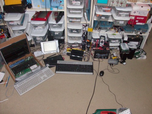
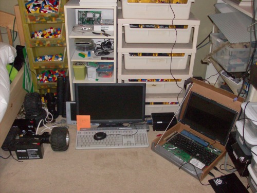
This is where i spend most of my time working on this thing. yes that is my laptop on the left, and yes it is in a cardboard box. :)
UPDATE 10/31/12=====================================================================================
Not a really big update, but my motor driver relays came in the mail yesterday. WOOT! I hope to have at least 1 of the motor drivers done on the weekend, and you guys will be the first to know about it ;)
also, the connector on my I/O board is for a mini IDE port, but all I have is a 3.5in hard drive. I looked around the internet, and found lots of adapters for connecting a 2.5in drive to a reg IDE port, but none going the other way, for connecting a full sized hard drive to a mini IDE port, anyone heard of such a thing?
UPDATE 11/5/12================================================================================
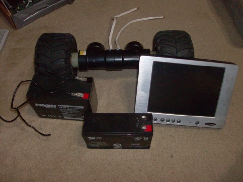
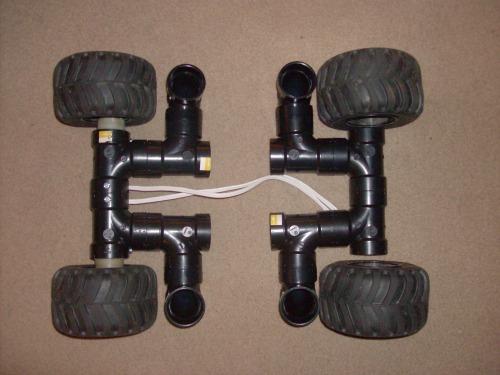
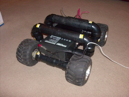
Over the weekend I got a few things done, The front axel is finished, wired and everything, here is a pic with the front wheels on and with a cupple other items for size comparision:
that battery you see with the wires dangling off it is one 12v 10ah battery off an electric bike, I have two, and I might put both on depending on battery life, motor power etc. The one in front is a 12v 6ah that I was going to use originaly.
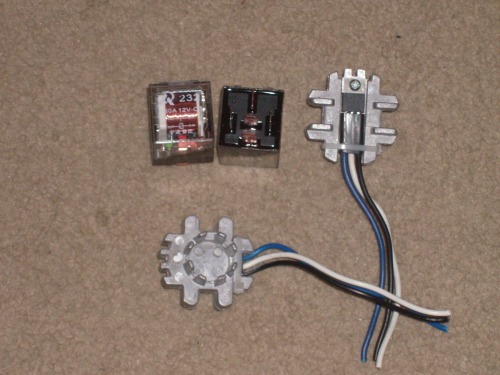
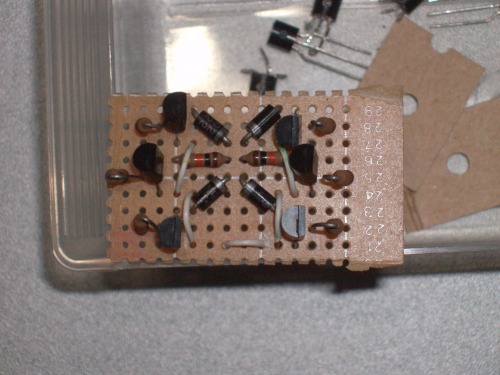
here you see the major components of one motor drive circut:
the relays claim to be 80 amp, not sure if I belive that, but the switches running the motors originally were only rated for 20 amps anyway so I dont think I will smoke them. the MOSSFETs will be wired in parallel for LOTS of current handling ability.
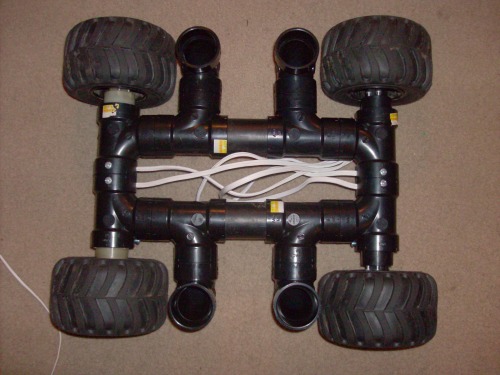
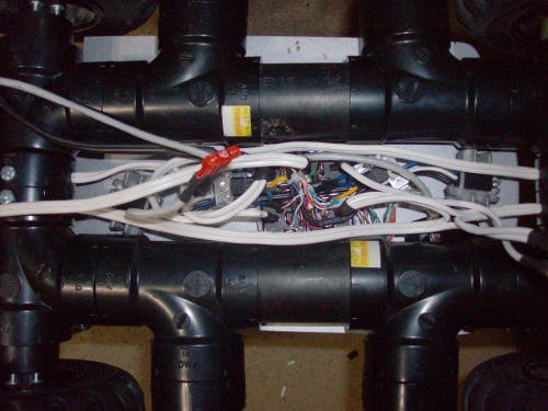
here is the new setup, I will have 4 more elbows to be mounted on pipes sticking up out of the elbows by the wheels to form a nice roll cage:
I dont have any pics up yet, but my family's dishwasher broke a little while ago, and I get to have anything I can salvage from it before it goes to the dump, so I have this big sheet of shiny stainless steel that came off the front of the door for a skid plate and possibly shell of the robot when it is done, I also have a cover from a 200 disc changer cd player that is painted a nice black in case I run out of metal.
also, two cordless drills from harbour freight should arrive before monday for the rear axel, once they come I can get on with the finishing of the mechanics of the robot.
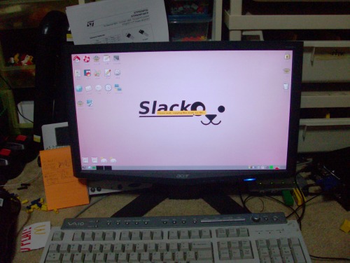
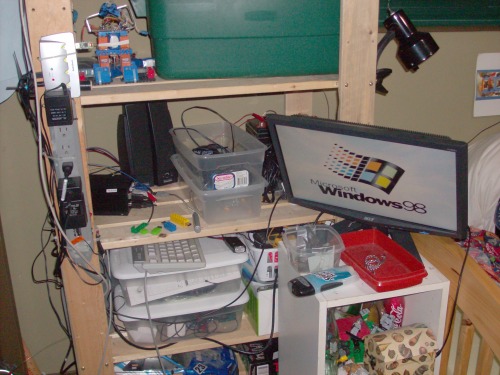
on the software side of things, for testing I got rid of that tiny touchscreen and replaced it with a 18.5 in lcd as shown:
I tried to install puppy linux on one of the comps, but kept getting this error message:
This kernel requires the following features not present on the CPU:
pae cx8
Unable to boot - please use a kernel appropriate for your CPU>.
anyway, either I have to find a different distro, or get around to installing that 1.8 ghz pentium board in one of the comps. Any suggestions?
UPDATE 11/6/12====================================================================================
got some time to cut a little pipe to show you what my frame is going to look like:
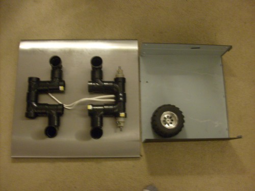
here is the sheet metal I will be using for the skid plate/shell (see last post) with robot parts for size comparision.
finally got that screen blacked out, GPS demo: this is on the touchscreen.
also, the two motherboard types I have at my disposel are
anyone know a linux distro that would run on either of those?
I am a little worried about the weight of my robot, the tyres I am using are very soft, and they might compress with too much weight when the robot is completed. one of my friends suggested that if that happens I should fill the tyres whith expanding foam, might work.
UPDATE 11/13/12===================================================================================
While the LMR servers were down, I got some work done.
First off, I got the two rear motors, wired them and mounted them.
mockup of what it might look like
 .
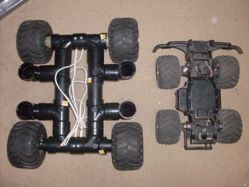
.size comparision between the other outdoor platform I was considering using
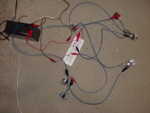
prototyping the relay/mosfet buffer board
and the compleated buffer board, sans 16 connecting wires.
the motor driver compleated, wired and ready to go. Each side (two motors) is connected to a fuse, and the whole thing is also wired to a fuse before going to a battery. you can see in the video opperating off +5v inputs.
.
cupple of random pics, one of all the fittings gone into the robot so far.
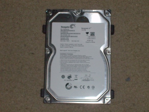
and the hard drive that will serve the robot, when I get around to buying a sata to mini IDE adapter
speaking of hard drives, the computer part of the robot has stalled until I can figure out how to disable that power moniter feature I mentioned earlier. Thanks to some help from LMR I was told about a distro that would run, and it started installing fine, until the power chip killed the power.
UPDATE 11/15/12================================================================================
I talked with the guy that gave me the PCs, disabling the power chip is just as simple as applying power to the "on" lead, waiting till the comp starts to boot up, and removing power. facepalm. so anyway, Thanks to the help from 6677 and antonio.caciuc I got Slako Puppy linux up and running on one of the comps.
Right now I am removing and inserting a spade connecter into the main fuse as a power switch, but that isnt going to fly when the robot is fiinished, so here are the two options I am considering for the power switch
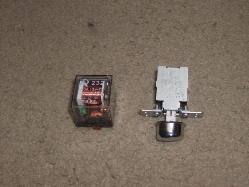
that spare relay, from the 5 pack on ebay rated 80 amps, and could be swiched by a small toggle, plus it would dubble as a power indicator, and the power swich from that dishwasher I mentioned earlier, rated 15 amps at 125v, but with two poles, so probably dubble, havent made my mind up yet.........
UPDATE 11/19/12========================================================================== I quickly wired up a two breadboard circuts using a picaxe 18m2 that let me either control GPS using serial commands thru the picaxe terminal or control using a 27MHz tx/rx. I also got to drive the thing around for the first time, and I uploaded a vid of it for you guys. If you watch right to the end, there is a little supprise involving not applying locktite to some places that should have had it applied. the battery I am using in the video is a real piece of junk, I will be using a different one on the compleated robot. probably a 6v 10ah and a 12v 10 ah wired in series.
UPDATE 11/20/12===========================================================
Well, the embedded video seems to be down, so if you scrol down just a little more, you can see the youtube links for the new videos.second comment from the top.. I might not have any updates for a bit, as the next step will be cutting/forming/mounting the skid plate/lower shell, and that might take a while. actually all the guts will fall out of the bot without the skid plate in place, for the video I got around that by tapeing a pice of cardboard to the bottom of the robot. Also, now that I have the comp up and running, I need to teach myself to program it, and I don't even know where to start, I am asking around on some linux forums and vaious other places for some help finding a development enviroment for a language that is well documented and supported, and allows acess to serial/parallel/usb I/O. while I am at it, any of you know? I know you are lurking 6677, do you have the answer? ;)
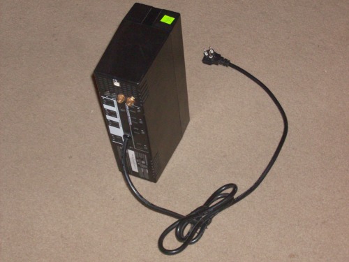
UPDATE 1/7/13============================================================================== I managed to get some work done over the holidays: First, I bought a dirt cheap broken UPS to rip the battery out of:
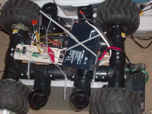
New battery on robot:
I decided the frame did not need to be as long, so I shortened it. Before:
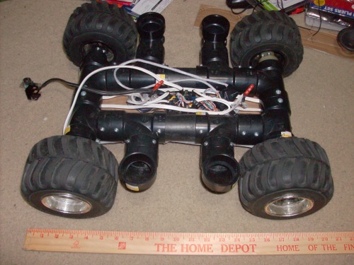
and after:
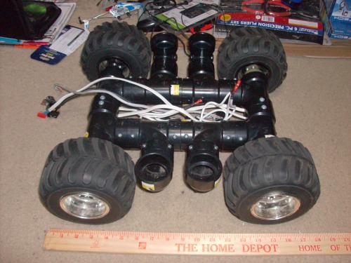
I got it all buttoned up nicely in an old cd player shell with a little bit of tin to complement it:
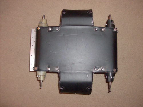
the little piece of aluminum channel on the front is a sensor shelf for avoidance.
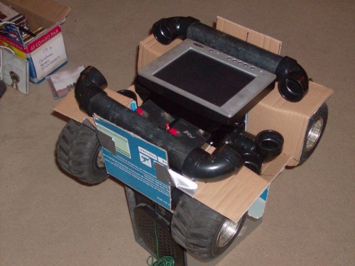
here is a prototype of what I thought it might look like before I got wiser :)
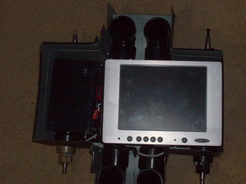
a little pic with the batterys screen and cpu in place:
speaking of batterys, I am planning on using, as mentioned before, 1 12v battery from that UPS, and two 6v batterys wired in parallel together, and then in series with the 12v one, for a total of 18v 10ah all around.
warning rant ahead:
So, I have a thumb drive with slacko puppy linux on it, that has not changed. I was thinking it would also be nice to have one with WinXP, to run roborealm etc. I have a WinXP disc, but, the comp does not have a disc drive. I have two drive enclosures, one with IDE in and firewire out, the other one with sata in and USB out, and only IDE disc drives. So those are out. No problem, I will just copy the disc files to a thumb drive. Now, it will not boot from a thumb drive with the CD files on it. Frantic googleing, found a page that claims to show you how to do just that. has a zip file with some programs and DOS files, make a DOS startup disc on a flash drive, copy the files over, IT BOOTS! except, one of the utilities I need to use in DOS is in like Swaheli or something. Wonderful. Think, hey, maybe I can just copy the XP files to a thumb drive and run the Setup.exe file. Boot slacko puppy linux, remember you cannot run .exe files in linux. Make dos boot disc, and copy win98 files over, boot, install win98 think, great, now I have got it. run the setup.exe file. starts installing OOOO almost there.... once setup has copied all the files it needs, reboots to start installing...... BLUE SCREEN OF DEATH!! wonderful. so now, I am kinda stuck. I need a sata disc drive.....
I now have 4 functioning OSes depending on which comp, (remember I got two, and left one alone?) or thumb drive I use: DOS, Win98, WinXP embedded, and Slacko Puppy Linux. And still no WinXP Pro. At this point I am almost ready to slap Bill Gates in the face, and yet I still want his software. Go figure...
========================================================================================================
When complete, Navigate via GPS, colision avoidance sensors, and machine vision
- Actuators / output devices: possibly servos, 4 cordless drill motors, touchscreen monitor
- Control method: 27MHz RC system for fail-safe
- CPU: Custom computer with a 1.8GHz processer
- Operating system: windows 98, windows XP Embedded, DOS, Slacko puppy linux, Soon WinXP Pro
- Power source: 12V 10AH Lead Acid, Two 6V 5AH in parallel
- Programming language: Python, machine vision with Roborealm
- Sensors / input devices: SRF-04 sonar, GPS, camera, Maxbotix EZ0 sonar, touchscreen monitor
- Target environment: outdoor