


Global Domination Robot (GDR) Mk III
As it's been some time since the completion of the GDR Mk II, and many parts of the world have not yet fallen under the shadow of my power, I have decided to begin work on the Mk III version to work out many of the details that will be needed in future larger and more heavily weaponized platforms, especially regarding navigation.
I plan to build the Mk III sequentially to develop its navigation capability, and would like input from all of the smart folks on here. Here is the game plan:
1. Chassis, power, sensors, and processor.
2. Receive coordinate and Navigate to location (dead recon).
3. Detect obstacles, move around obstructions,
and still keep track of where it is and where it needs to go.
4. Establish wireless connectivity to receive movement orders.
5. Video relay through wireless connection
and ability to directly control the GDR Mk III from my lair (switch between autonomous and remote control)
To begin, I'm going after steps 1 and 2 above. I have an extra Uno here, as well as a motor shield and various other components. I think unlike the previous GDR versions, I will use a pre-made chassis and engine. So, my materials list:
a) Tamiya tracked chassis with dual motors and gearbox. (open to input that doesn't get too expensive)
b) Arduino Uno
c) arduino motor shield
d) LIPO Battery (input on this greatly appreciated)
e) Voltage regulator so I can power arduino and
motors on same battery
f) LCD Keypad to input movement order coordinates (never worked with this before, would like input on whether or not this will conflict with other components I am attaching to the arduino, like the motorshield)
g) Encoders for motors
h) Compass (I see these for sale from anywhere from about $5 to $150... am I wrong to go cheap here?) h)
Update 17 JAN 2016:
I've ordered the chassis from Sinoning.com, and have just placed my order for the components that I don't have laying around the workshop. Since I'm waiting on the post from China to the US, I've worked up some schematics for how I think I'm going to build this thing. The only part that I should have to fabricate myself is a plastic plate to mount on top of the chassis and hold the arduino and sensors.
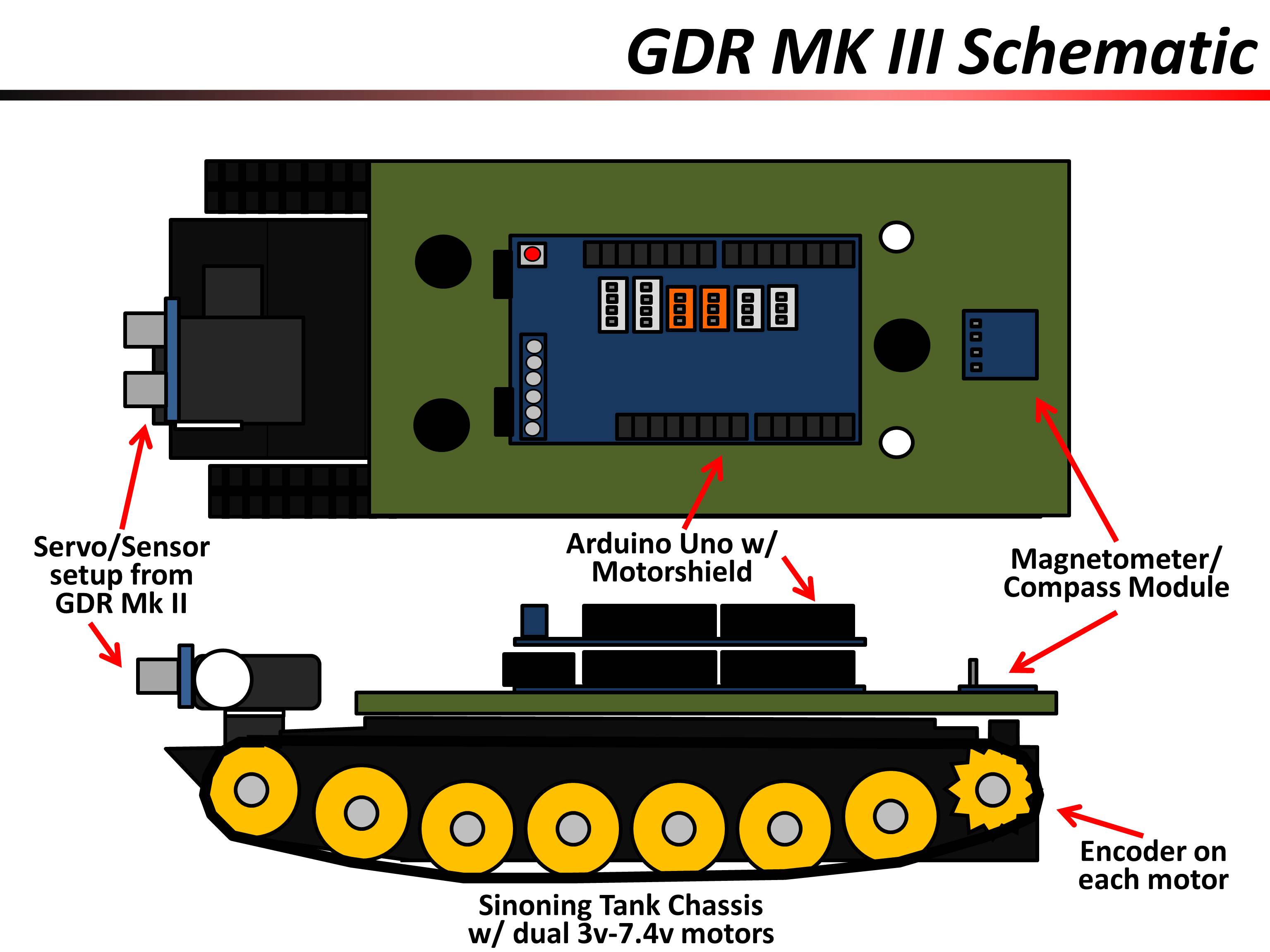
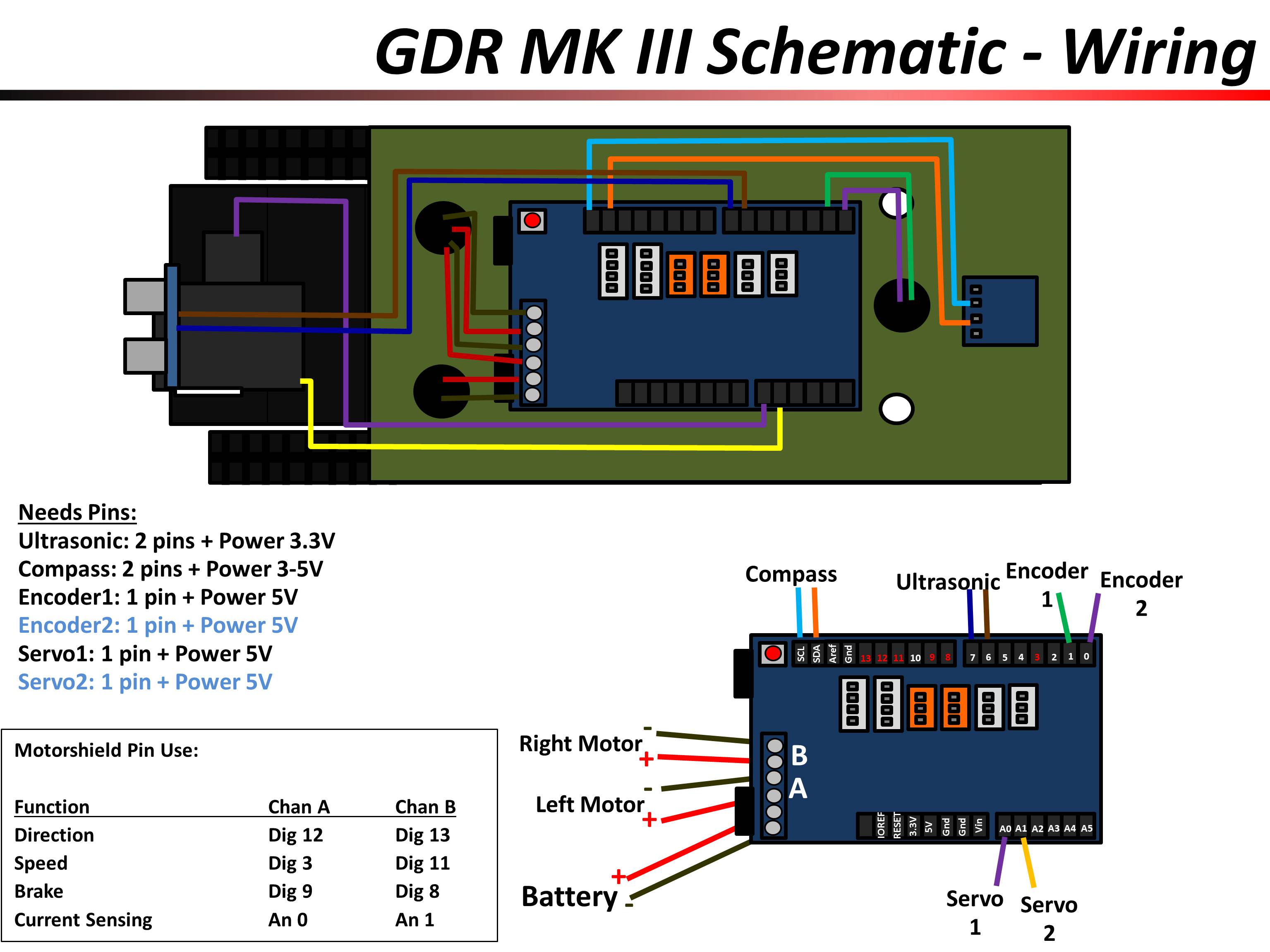
I've also been working out this plan for wiring. You will note that I dont have any of the power worked out for my components yet (except the motors). I've ordered a 7.4v 2000mAh LIPO battery. Can I just run the power for all of the sensors and servos out of the 5V and 3.3V pins on the arduino motor shield?
Update 4 FEB 2016:
The chassis finally came in from Sinoning. Wow, that was slow. I chose the cheap (free) option to have it go through the post from China, and the torture (no disrespect meant for those undergoing actual torture) of waiting was made worse by having the ability to watch its progress through various sorting facilities via usps.com.
The chassis exceeds my expectations. It came fully assembled, which was a surprise for me, and I could immediately wire up the motors to a battery pack to make it run. It has a switch built into the bottom, which I don't remember from the description, but is an added bonus. I usually include a power switch on my projects, so this just makes it easier. The front compartment of the chassis fits the mini-servo that I'm planning on using for an ultrasonic rangefinder just about perfectly.
Areas that need some work:
1) The battery compartment isn't long enough for my LIPO battery (I think it was originally designed for several AA batteries, but there are no terminals built in). I'm going to have to cut out a hole in the front of the battery box, which should work fine since there is extra room in front of it, but my dremel recently died and I have to aquire a new one.
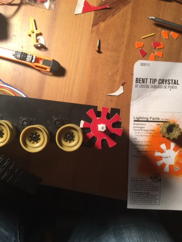
2) The disks for the optical encoders that I bought are too thick to fit in between the drive sprocket for the tracks and the chassis. I've stencilled the shape of the disks (more like sprockets themselves actually) onto some thin cardboard and will cut them out and see if I can mount them in that thin gap. Otherwise I'm going to have to put them on the outside of the sprockets and fabricate something to hange the encoders out there. More to follow on this one.
Update 8 FEB 2016:
I built encoder disks that fit between my drive sprockets and the chassis out of cardboard (I used the original thick plastic ones as a stencil), and tested that they work.
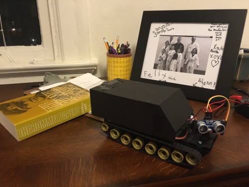
I also built a casing out of polystyrene to cover all of the upcoming mess of wires. This was midway through the process, it looks a bit nicer now that I've peeled off the tape (used to keep it together while I was cementing it) and hit it with a coat of black spray paint. Unfortunately, the only plastic I could find at Hobby Lobby was this really thin and flimsy stuff which will be okay for cosmetic purposes, but I'm going to have to replace before I try mounting anything up on the roof. I found thicker plastic today at Home Depot, so it will work out in the long run.

20 FEB 2016:
Designed and built a turret for the servo and ultrasonic rangefinder on the front of the GDR from the thicker plastic that I found at Home Depot. Cutting the pieces with my dremel was adequate and created a solid structure (I designed interlocking components), but cosmetically isn't very impressive. The dremel created slag which had to be sanded off, and resulted in less than perfect edges where the pieces come together. Fully functional, sturdy and durable, but a CNC cutter or 3D printer might be in my future.
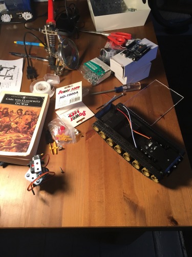
I used a small breadboard to create a power system for the GDR. 7.4V comes in from the LIPO battery in the chassis, and the board puts out 7.4V for the motors, and a strip of 5V pins for all my components (also integrating a pair of capacitors to hopefully stabilize power flow (especially for the use of the ultrasonic sensor). The power board works great as far as I can see so far, but the prototyping board I used is a little big to fit comfortably on the deck of my chassis (it's on the desk beside the GDR in the photo). before field testing I may use the dremel cutter and take down the size of the board to just the sections I am using.
I rigged up the encoders on the back of the GDR and they work, but I'm not happy with the stability of the way they are mounted. I'm going to have to design and cut a frame for them out of plastic to get them stable enough for field testing. I've started on the code, and have it ready to run as a standard obstacle avoider (this will be a loop running while the GDR navigates). I'll post a video when I load it onto the arduino and get the robot zipping around.

24 FEB 2016:
Well, it "zips" sufficiently at this point (sorry, no video yet... but then again, who really wants to see just another obstacle avoider at this point?) acting as an obstacle avoider. I was able to fit the power board up onto the main deck without cutting it down. Had to play with the wiring to get everythnig to work, and realized that I have a couple dead pins on my homemade power board that don't work. I'll have to check the soldering to see where I scewed that up. The ultrasonic works great, but there wasn't room for my jumper wires in the configuration from the above picture. I had to flip the ultrasonic upside-down to fit the wires, which is a major bummer. I'll fiddle with it in the future to see if I can get them to comfortably come out of the bottom.
For my next trick I will have to straighten up the mounting for the encoders and the compass. After that it should be a fun little exercise to work through the mathematics of navigation, and how to make the machine do it. Looking ahead beyond that will come questions of destination input (ie LCD keypad vs bluetooth or wifi. This will be autonomous, so no remote control required.
27 FEB 2016:
I figured out how to use the compass (3-axis magnetometer), and wrote some code to make the GDR turn to an azimuth and drive that direction. Very happy with the results. For initial testing (as you will see in the video) I just taped the magnetometer to the back of the robot. This worked to prove the concept of the robot turning to an azimuth and traveling along it, but what you don't know is that I've set the target azimuth at 270 degrees, and the robot was consistently heading at about 225 or so degrees (our historic home is laid out with 19th century military precision, so this robot should be heading directly for the west wall, which it is not). As you'll see in the picture I cut a hole in the top of the GDR covering case and mounted the magnetometer on top (you see it held there with electrical tape). Now the GDR Mk3 turns in precisely the correct direction and keeps moving in the correct direction (as verified by my trusty M2 compass with declination constant). I have noticed a slight variance when the GDR drives past a certain electrical socket in my second floor hallway, so I may have to integrate some of the code that I see available online to compensate for external magnetic fields. I will save this for the end of the GDR 3 project though, because I am starting to fear that my coding for this many planned functions may exceed the capacity of the single arduino that I am using.
My next step will be more securely mounting the encoders and integrating data from them into the main loop. I want the GDR to turn to a directed azimuth and drive a directed distance at this azimuth. Right now my device to input this into the GDR is a USB link to the arduino - I need to start planning for either an LCD and keypad interface or a wifi connection to send movement directions to the GDR.
29 FEB:
Mounted one of the encoders on the port-side drive sprocket. My plan was to run some tests to figure out how far the robot moved for a set number of "hits" on the optical encoder. I was getting some pretty drastically different distances (for 100 hits it varied from 96" traveled down to only 72" traveled). I tightened down the reference disc on the drive sprocket and got slightly better results, but it wasn't until I slowed down the speed of the motors to half speed that my distances started coming back consistently. It should be said that at half speed the distance traveled for 100 hits is significantly less (16.5" every time), so that leads me to believe that at full speed the counter was missing counts at full speed. With an accurately moving robot, I am ready to move to my next problem which is determining a path from current location to a destination coordinate.
Navigates to Coordinate in order to control territory/enforce my will on the populace
- CPU: arduino uno
- Programming language: C++
- Sensors / input devices: encoders, compass