


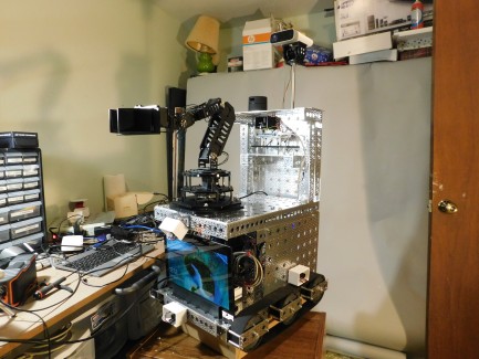
Meet Antwerp
So, my first big milestone goal for Antwerp is to have it fetch a beer from the ‘fridge. While this may sound like a highly frivolous goal (mostly because it is), if you think about what it would take to get a robot to do that, it’s actually pretty ambitious. You’ve got environment mapping and navigation to find the ‘fridge. You’ve got shape recognition to recognize the beer bottle. You’ve got creating a mechanical system able to open the door of the ‘fridge, etc., etc… So, if I build a robot that can do all those things, it will also be able to do some things that might not be quite so frivolous.
I came at this with about 40 years of coding experience, but zero years of electronics experience, or any of the other skills it will take to pull this off. At the end of the day, it’s a hobby for me. I’m doing it for fun. So, I have the luxury of learning as I go with no pressure to get it done within a timeframe or any of the stress that might come along with trying to do it for a living.
These are the main hardware components that make up Antwerp:
- The platform at the base of the robot is from a kit I bought on the “Servo City” site. It’s called the “Agent 390”. It’s a 12 by 18-inch platform with tracks on the sides for movement and motors to run the tracks.
- The rest of the aluminum structure of the robot is made up of more "Actobotix" stuff I got from Servo City sort of “ala carte”.
- I designed all the plastic mounting hardware with Fusion 360 and created it using a “Prusa mk3i” 3D printer.
- The track motors and six ultrasonic range sensors that are mounted on the sides of the robot are all connected to an Arduino “Mega 2560” controller card with motor and ethernet shields that is mounted onto the base platform, inside the “Body” of the robot.
- The robot also has its own independent, ethernet network including a router and wireless hotspot.
- Everything is powered by a big LiPo battery rated at 38,000 milliamp hours.
- The master computer that will run my software framework will also be mounted at the base of the robot. It’s an MS Surface Pro mounted at the front of the base acting like sort of a face for the robot.
- At the second level moving up, there’s a 6 DOF arm that I got as a kit from Trossen Robotics. The model is called the “Widow X”. The arm is controlled by an Arbotix Controller card that communicates with the master computer using serial communication over USB.
- The oversized (and hopefully beer-worthy) gripper on the arm is custom. I designed it with a rack and pinion setup that can open to about four inches. The “fingers” of the gripper extend about two and a half inches out from the base. Like all the other plastic pieces, I made it using the 3D printer. The gripper that came with the arm only opened to a little over an inch and used a sort of hinky lever system to move the fingers. (Definitely NOT beer-worthy.) To be clear that’s about the only complaint I have with the arm. On the whole, it’s strong, versatile and generally cool.
- Behind and above the arm is a digital compass to give directional awareness.
- There’s a 360-degree LIDAR sensor mounted on the top plate of the robot for environment mapping and navigation.
- Above it all, there’s an MS “Kinect” depth camera for shape recognition, detailed 3D distance measuring, point clouds, straight RGB video, directional sound analysis, etc… It’s mounted on a pan and tilt setup I got from Servo City. It will connect directly to the master computer over USB.
- There’s another Arduino Mega that controls things at the top level of the robot including the compass, the servos for the pan & tilt camera mount and control for the LIDAR sensor.
- Finally, there will also be an Intel RS 435i depth camera mounted on the “wrist” servo of the arm that will kick in when the arm is in operation. I have the camera and have it working with my framework, but I still need to make the bracket it will be mounted on.
I’m a long way from finished with the project, but I have gotten all the pieces working and able to interact with my software framework independent of each other except for the Lidar. Just haven’t gotten around to playing with it yet. I finished the framework a couple of months ago, so now it’s all about making it actually start to do things. It’s that journey we’re documenting on our Youtube channel named “wearerobby”.