


gesture controlled robot using accelerometer
Step 1:-introduction
welcome to our channel s-r tronics...we are making some project using arduino..so guys this is our new and project...gesture hand control arduino robot using adxl335 accelerometer...and another all project coming soon..this robot can moved by hand control using adxl335 accelerometer..
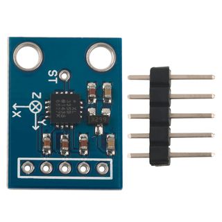
the 3 axis ADXL335 from Analog Devices. This is the latest in a long, proven line of analog sensors - the holy grail of accelerometers. The ADXL335 is a triple axis MEMS accelerometer with extremely low noise and power consumption - only 320uA! The sensor has a full sensing range of +/-3g.
There is no on-board regulation, provided power should be between 1.8 and 3.6VDC. Board comes fully assembled and tested with external components installed. The included 0.1uF capacitors set the bandwidth of each axis to 50Hz.
now lets gooooo..
Step 2: -circuit Components
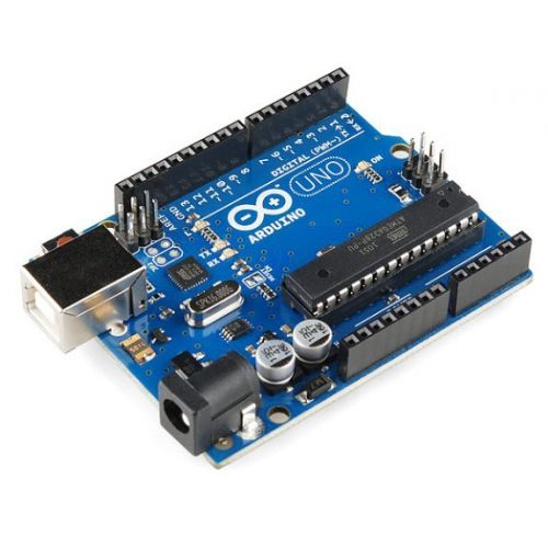
1:arduino uno
2:-adxl335 accelerometer
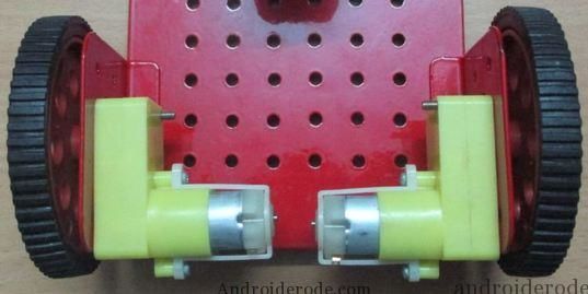
3:-two dc motor
4:caster wheels
5:-battery(powerbank)
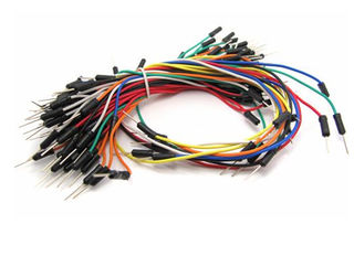
6;-jumper wires
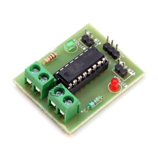
7:l293d motor driver
8:one chassis
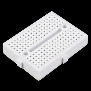
9:-mini breadboard
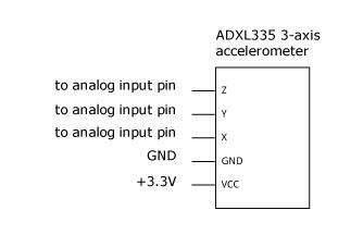
Step 3:-adxl335 Connection
here.
x pin of adxl335 is connect to analog pin of arduino.
y pin of adxl335 is connect to analog pin of arduino
gnd pin of adxl335 is connect to gnd ...
vcc pin of adxl335 is connect to 3.3v of arduino...
must remember this connection.............of vcc
Step 4:-circuit Diagram
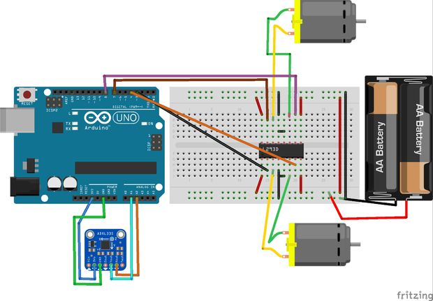
here is the circuit diagram of this robot..
in arduino uno analog pin;--a1 and a2
digital pin;--3,4,7,8
a1---------x pin to the adxl335
a2---------y pin to the adxl335
3pin of arduino-------2 pin of l293d
4pin of arduino-------7pin of l293d
7pin of arduino-------10pin of l293d
8pin of arduino-------15pin of l293d
sooo,3,4,7,8 pins are connected to the l293d motor driver
Step 5: -if You Used As L293d Ic
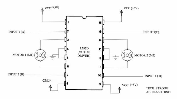
if you use l293d ic instead of l293d motor driver..
even its will be easy for connection.... l293d ic have 16pin... 1,8,9 and 16 pin connect to +5v.
and 4,5,12,13 pin connect to gnd...
input 1,2,3 and 4pin is connect to arduino pin..
output is connect to left motor and right motor..
input 1 and 2 is connect for left motor..
and input 3 and 4 is connect for right motor..
Step 6:-uploading the Code
int LMT1=7,LMT2=8; // Motor Terminals M1
int RMT1=3,RMT2=4; // Motor Teminals M2 int X=A2; // X Axis is given to A2 int Y=A1; // Y Axis is given to A1 int Xvalue,Yvalue; // Variables for storing the value
void setup() { pinMode(LMT1,OUTPUT); // Motors are declared as output pinMode(LMT2,OUTPUT); pinMode(RMT1,OUTPUT); pinMode(RMT2,OUTPUT); pinMode(X,INPUT); // A2 & A1 pins are declared as input pinMode(Y,INPUT); } void loop() { Xvalue=analogRead(X); // X axis values stored in a variable Yvalue=analogRead(Y); // Y axis values stored in a variable
if(Xvalue>=345 && Xvalue<=360 && Yvalue>=340 && Yvalue<=355) // The boundary values are set to stop the motors { Stop(); } else if(Xvalue>=388 && Xvalue<=410) // The X axis values are used for vertical movement { forward(); } else if(Xvalue>=270 && Xvalue<=305) { back(); } else if(Yvalue>=280 && Yvalue<=300) // The Y axis values are used for horizontal movement { left(); } else if(Yvalue>=375 && Yvalue<=410) { right(); } }
void forward() // forward function is defined { digitalWrite(LMT1,HIGH); digitalWrite(LMT2,LOW); digitalWrite(RMT1,HIGH); digitalWrite(RMT2,LOW); } void back() // backward function is defined { digitalWrite(LMT1,LOW); digitalWrite(LMT2,HIGH); digitalWrite(RMT1,LOW); digitalWrite(RMT2,HIGH); } void left() // left function is defined { digitalWrite(LMT1,HIGH); digitalWrite(LMT2,LOW); digitalWrite(RMT1,LOW); digitalWrite(RMT2,HIGH); } void right() // right function is defined { digitalWrite(LMT1,LOW); digitalWrite(LMT2,HIGH); digitalWrite(RMT1,HIGH); digitalWrite(RMT2,LOW); } void Stop() // stop function is defined { digitalWrite(LMT1,LOW); digitalWrite(LMT2,LOW); digitalWrite(RMT1,HIGH); digitalWrite(RMT2,HIGH); }
now.....copy the code and paste in arduino programming....
at 1st compile the code..then upload to your arduino board.
Step 7:-result
for action this video link will be helpful to make this robot.
and try to subscribe our channel s-r tronics and likes and comment also..thanks guys...