


G-sensor Controlled Arduino Robot
hello guys...
this is our project...
Smartphone Controlled Arduino Robot Car via Bluetooth With G-sensor app..that the robot will move depending on the slope of your smartphone.
Joystick can be controlled by moving the slider with your finger.
Step 1: COMPONENTS
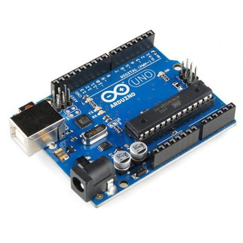

1:-arduino uno
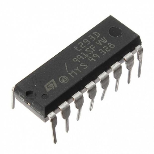
2:-l293d chip
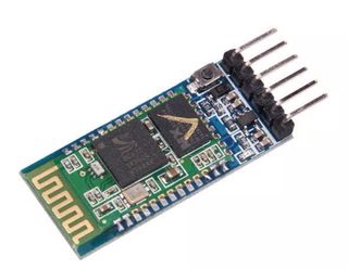
3:-bluetooth module hc-05
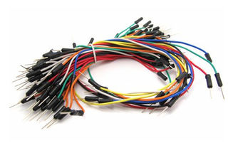
4:-jumper wires
5:-a smartphone
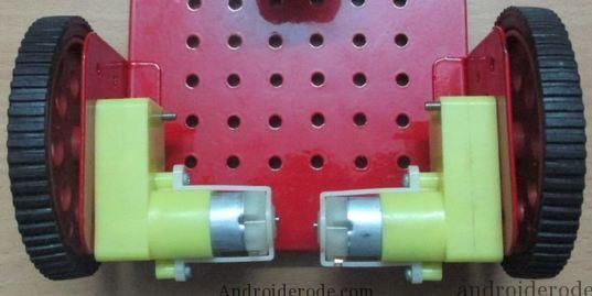
6:-two dc motor
7:-one chassis with caster wheels
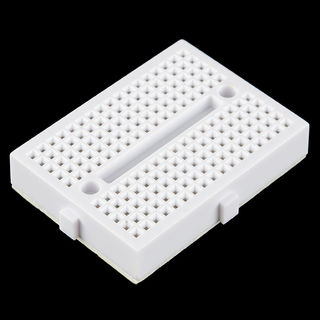
8:-breadboard
Step 2: L293d Connection
l293d have 16pin..
8pin and 16pin of l293d is connect to +5v
4,5,12,13pin of l293d is connect to gnd
1pin of l293d is connect to 10 pin of arduino
2pin of l293d is connect to 6pin of arduino
7pin of l293d is connect to 7pin of arduino
9pin of l293d is connect to 11pin of arduino
10pin of l293d is connect to 9pin of arduino
15pin of arduino is connect to 8pin of arduino
and
3and 6pin of l293d is connect to left motor
11 and 14pin of l293d is connect to right motor
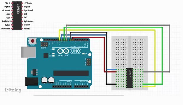
Step 3: Circuit Diagram
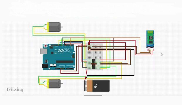
before
i have discussed about l293d connection and motor connection to arduino...so plz follow this circuit..
and for bluetooth module...we have to do..
gnd pin of bluetooth is connect gnd
+5v is connect to +5v
tx is connect to 2 pin of aarduino
rx is connect to 3pin of arduino...
so this rx and tx connection is most important for this project...
must remember that..
Step 4: Application
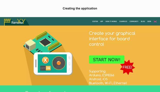
RemoteXY is easy way to make and use a mobile graphical user interface for controller boards to control via smartphone or tablet.
RemoteXY - https://goo.gl/UFCKTS
plz follow this link...and add remote xy library to arduino zip file
and follow this video for making app..
https://www.youtube.com/watch?v=0pnv_oE9K6w&t=353s
Step 5: Uploading Code
plzz copy the code....and
paste to arduino..
// RemoteXY select connection mode and include library
#define REMOTEXY_MODE__SOFTSERIAL
#include <softwareserial.h>
#include <remoteXY.h>
// RemoteXY connection settings #define REMOTEXY_SERIAL_RX 2 #define REMOTEXY_SERIAL_TX 3 #define REMOTEXY_SERIAL_SPEED 9600
// RemoteXY configurate #pragma pack(push, 1) uint8_t RemoteXY_CONF[] = { 3,0,24,0,6,5,0,2,0,3 ,3,18,7,2,79,78,0,79,70,70 ,0,5,16,42,10,40,40,2 }; // this structure defines all the variables of your control interface struct {
// input variable uint8_t switch_1; // =1 if switch ON and =0 if OFF int8_t joystick_1_x; // =-100..100 x-coordinate joystick position int8_t joystick_1_y; // =-100..100 y-coordinate joystick position
// other variable uint8_t connect_flag; // =1 if wire connected, else =0
} RemoteXY; #pragma pack(pop)
///////////////////////////////////////////// // END RemoteXY include // /////////////////////////////////////////////
#define PIN_SWITCH_1 13
//define right motor control pins #define right_motor_A 8 #define right_motor_B 9 #define right_motor_speed 11 //enable pin
//define left motor control pins #define left_motor_A 6 #define left_motor_B 7 #define left_motor_speed 10 //enable pin
//define two arrays with a list of pins for each motor uint8_t RightMotor[3] = {right_motor_A, right_motor_B, right_motor_speed}; uint8_t LeftMotor[3] = {left_motor_A, left_motor_B, left_motor_speed};
//speed control of motors void Wheel (uint8_t * motor, int v) // v = motor speed, motor = pointer to an array of pins { if (v > 100) v=100; if (v < -100) v=-100; if (v > 0){
digitalWrite (motor [0], HIGH); digitalWrite (motor [1], LOW); analogWrite (motor [2], v * 2.55); } else if ( v<0 ){
digitalWrite (motor [0], LOW); digitalWrite (motor [1], HIGH); analogWrite (motor [2], (-v) * 2.55); } else{ digitalWrite (motor [0], LOW); digitalWrite (motor [1], LOW); analogWrite (motor [2], 0); } }
void setup() { RemoteXY_Init (); pinMode (PIN_SWITCH_1, OUTPUT); //initialization pins pinMode (right_motor_A, OUTPUT); pinMode (right_motor_B, OUTPUT); pinMode (left_motor_A, OUTPUT); pinMode (left_motor_B, OUTPUT); }
void loop() { RemoteXY_Handler (); digitalWrite(PIN_SWITCH_1, (RemoteXY.switch_1==0)?LOW:HIGH); //manage the right motor Wheel (RightMotor, RemoteXY.joystick_1_y - RemoteXY.joystick_1_x); Wheel (LeftMotor, RemoteXY.joystick_1_y + RemoteXY.joystick_1_x);
}
Step 6: Result
so guys follow the instruction for making this project..
and also folllow this link on you tube of our channel s_r tronics
https://www.youtube.com/watch?v=0pnv_oE9K6w&t=353s
so guys,,,..subscribe our channel and stay tuned with us..
do likes and comment in inbox...