


FRED solar roller
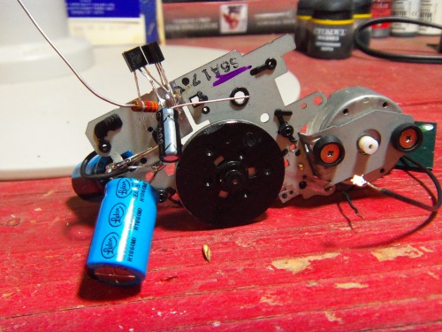
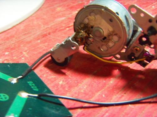
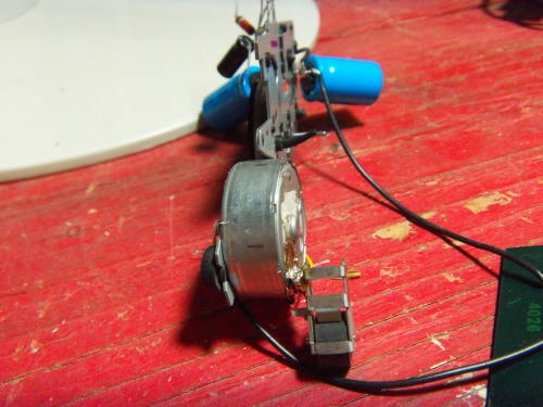
I have started finished work on my second robot. It uses a FRED solar engine, and is a really simple circuit; I salvaged a belt and pulley from a cassette player, and I am using it as the body; The belt will be used as the back wheel. A pinch roller I found in the same cassette will be used as a front wheel. It has been soldered directly to the motor. This has proven ineffective because the wheel is delicate and never stays put. Instead, I used some 16 gauge solid core wire to poke through two holes in the pinch roller. This was soldered in place. The other end of the wire was soldered on the motor where the wheel used to be. This new setup is much more stable and easier to adjust with pliers. I am in the process of getting the resistors soldered in. I have finished soldering the resistors in. It took a while because I was free forming it directly onto the body of the robot. I used the metal frame itself as ground. I have tested it with lamp light, and then in direct sunlight. I am pleased with its performance.
The parts I am used are:
1 - 2N3904 NPN transistor
1 - 2N3906 PNP transistor
3 - 1000uF capacitors
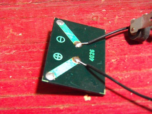
1 - 4.0V, 3 mA solar cell
1 - red flashing LED
1 - 0.47uF capacitor
1 - 330 10% tolerance resistor*
1 - 3,300 10% tolerance resistor*
- A whole lotta duck tape
Pictures of the robot:
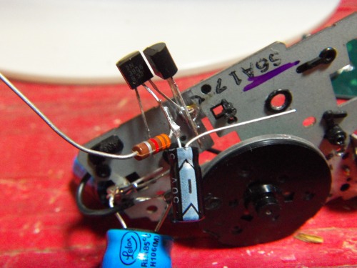

*these resistors are 20-30 years old; they have been in my grandpa's basement all this time. Which is why they are 10% tolerance
Credit for this solar engine goes to Ben Hitchcock.
Solar Roller:Charges capacitor(s) until sufficient charge is reached, then discharges.
- Actuators / output devices: 1 motor, plus belt and pulley. Taken from tape recorder
- Control method: none
- CPU: none
- Operating system: none
- Power source: 1 4.0V, 3 mA solar cell
- Programming language: none
- Sensors / input devices: none
- Target environment: indoors on a hard flat surface.