


FPV Squid Rover
My new rover with 8 wheels :-)
It is controlled by my FPV Control Station.
Added a video where i drive it....
But the bearing break in the end of the video :-(
And a nother FPV video.
Some features and parts:
- Top speed about 6-7 km/h.
- About 20 cm ground clearance.
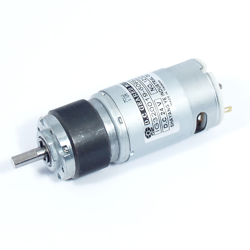
- 8 24 volts dc motors.
- 8 Monster Truck 10-Spoke Wheels
- Pan and tilt of the camera (Bearings to get a sturdy construction)
- Headlamp for the camera (a demolished flashlight).
- Siren to scare bad people.
- Daytime running lights.
- 1W 2.4GHz Video and audio FPV
- Using a HM-TRLR-S LoRa transceiver to control it.
- Text To Speech(Can send text from the Control station and the rover speak it)
- Water resistant compartments.
Below is a short work log and description how it works...
Motors and suspension
I made the motor mounts out of aluminium so i could fix the motors to the suspension arm.
I thought that would be enough but was a to weak so I had to fix a extra support and clamp with a hose clamp.
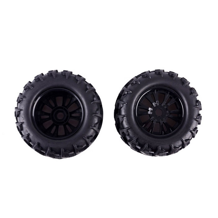
The HobbyKing wheels is a bit to soft and small, waiting on some bigger (15cm diameter) wheels from DX.
It is about 20 cm ground clearance and the suspension can follow the terrain.
Electronic and battery boxes
In the front and back of the rover i have a water resistant apartment for the electronic and battery..
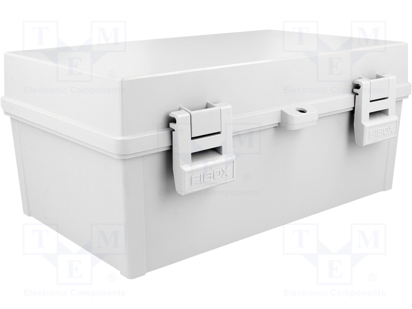
The inside of the box is covered with aluminum tape to protect against interference, this is probably completely unnecessary, but why not...
I have velcro on the bottom to fasten the batteries.
You can connect 2 batteries in parallel in both the front and back apartment (Total 4).
It also is a cable to connect batteries in series if you want.
It also is a cable to connect batteries in series if you want.
Power and motor controller
The front apartment contains the man power board and DC motor controller.
The motor controller is a PiBorg Diablo. In the picture bellow (right box) there is a Trex motor controller but i swapped it for the Diablo.
It is controlled via I2C from the Raspberry Pi in the back apartment.
I use a Cat6S cable to transfer the signal.
In the back apartment i have the Raspberry Pi, Wifi, ADC and Relay controller.
Bellow is the Relays that control power to:
- 1W 2.4GHz Video and audio FPV
- Daytime running lights.
- Headlamp for the camera (a demolished flashlight).
- Siren to scare bad people.
Her is the box with buck converters and i have started to connect everything.
Everything is connected.
- Top left is the ADC to read battery voltage
- Right of ADC is a LC-filter for the Raspberry Pi
- Under the ADC and LC is the Relay box
- Then the Raspberry Pi
- Bottom left is the power bord.
3.3V 5V, GND, I2C... - Bottom middle the Buck converter box.
- Bottom right the LCD to read IP of the rover.
- Under the Raspberry Pi (middle right) is the Wifi
- Box
The back apartment with WiFi antenna and siren.
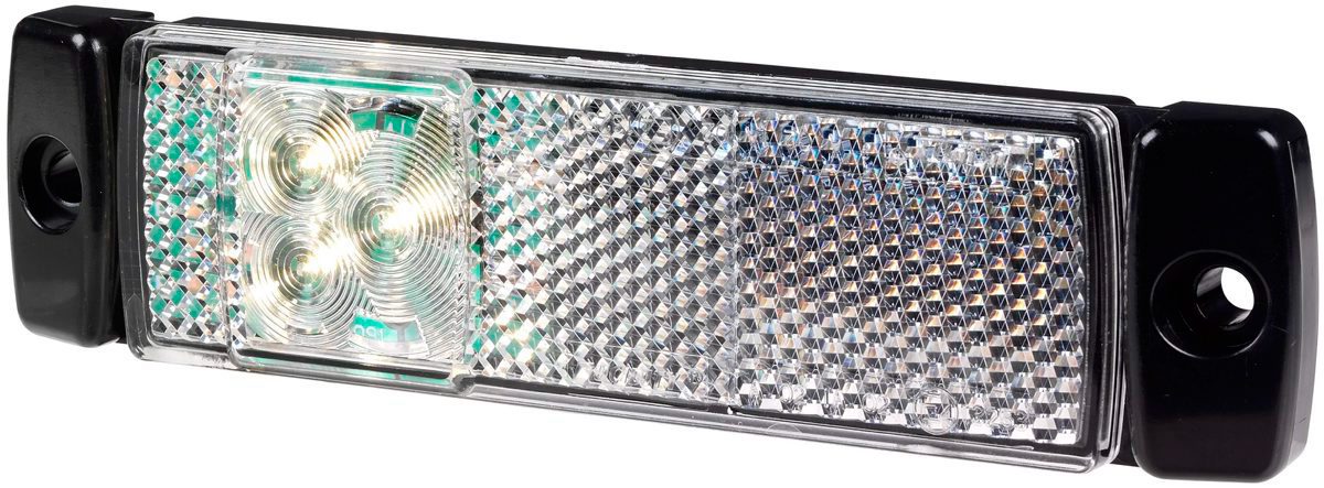
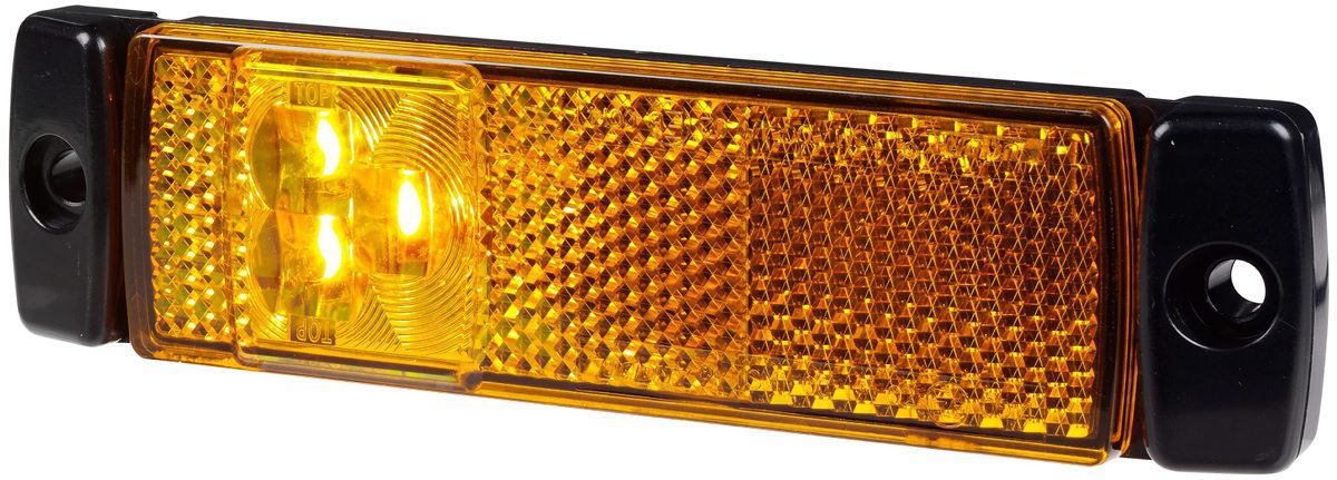
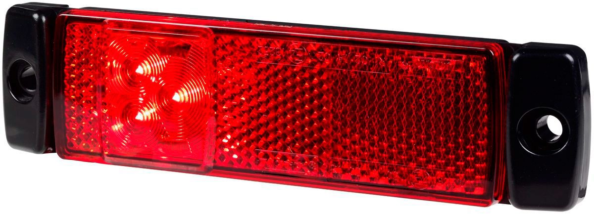
Lighting and power cables for motors
Connecting the lighting.
White on the the front, yellow on the sides and red on the back.
White on the the front, yellow on the sides and red on the back.
HM-TRLR-S LoRa transceiver and servo controller
On a small tower in the middle of the rover is the Camera, Video transmitter, HM-TRLR-S LoRa transceiver and servo controller.
The Pan and tilt on the picture bellow is not what i have on the finish rover. The one on the picture did not work so good, it was to flimsy and weak.
Bellow is the box for the HM-TRLR-S LoRa transceiver that i use to control and read status from the rover.
The inside of the box is covered with aluminum tape to protect against interference, this is probably completely unnecessary, but why not...
I use 2 buck converters, one 3.3V for the HM-TRLR-S and Servo controller and one 5V for the servos.
The servo controller is a Adafruit 16-Channel 12-bit PWM/Servo Driver.
The servo controller is a Adafruit 16-Channel 12-bit PWM/Servo Driver.
The signals from the Raspberry Pi to the HM-TRLR-S and Servo controller is transmitted on a Cat6S cable.
On a small tower in the middle of the rover is the Camera, Video transmitter, HM-TRLR-S LoRa transceiver and servo controller.
Bellow is a picture of the inside of the Camera box and power box.
- Inside the camera box is of course the camera and LC-filter for the camera power.
There are also a power cable for the headlamp going down to the Relay board. - In the power box is two LC-filter and a buck converter (12V) to feed power to the transmitter, camera and mic.
- The camera, mic and transmitter have separate LC-filters.
- Beside the power box is the video transmitter.
Camera Pan and Tilt
The first pan and tilt mechanism i built was to weak so a built a new.
The tilt has two bearings and is driven b belt from the servo.
The pan has one bearing and is connected directly to the servo.
Also added large ferrite bead on the servo cables.
Text to Speech
If you write a text on the keyboard on the control station and press enter the text will speak on the rover.
The LCD show a simple webpage where you can write the text and when you press enter it is handled by Steelsquid Kiss OS python webserver that send it to the rover.
The rover than use eSpeak as text to speech.
I have some small speakers and amplifier so i first made a speaker with a analog amplifier, but it sounded horrible.
Much noise from the servos and high frequency sounds, even though I used a LC-filter on the Raspberry Pi and amplifier.
So a switched it for PAM8403 Digital Amplifier Board. Now the sound is much better.Below i build the box for the speaker and amplifier.
It is a small plastic box but on the inside i glue some thin car muffler plates. So the thin plastic walls don't vibrate.
On the back is also some dampening foam.
(On this pictures it is the old analog amplifier)
(On this pictures it is the old analog amplifier)
The finish box with speaker grill and then fixed to the rover.
The speakers pointing down to protect against rain...
The speakers pointing down to protect against rain...
FPV rover
- CPU: Raspberry Pi
- Operating system: Steelsquid Kiss OS
- Programming language: Python
- Target environment: outdoor