


Flying Dutchman
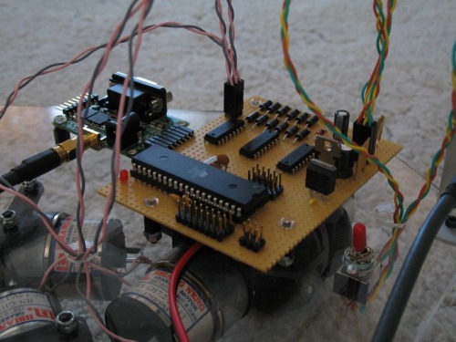
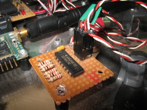
The "Flying Dutchman" is my second project. The project is more about a drive system then the robot itself. It is an omni wheel drive. An omni wheel robot can move in any direction. It moves in a very cool way (I think). I choose the ATMega32 because it has 3 PWM channels to control the 3 motors. The 6 AA batteries power both the motors and the microcontroller. Every calculation of motor directions and speeds are done in the microcontroller. I used 175 RPM gearmotors, for they have both power and speed.
At first I tried to use an open loop controller, but the robot did not move according to plan. Than I realized that the connection between the PWM cycle and the motor RPM is not linear. It is also dependent on the charge of the batteries.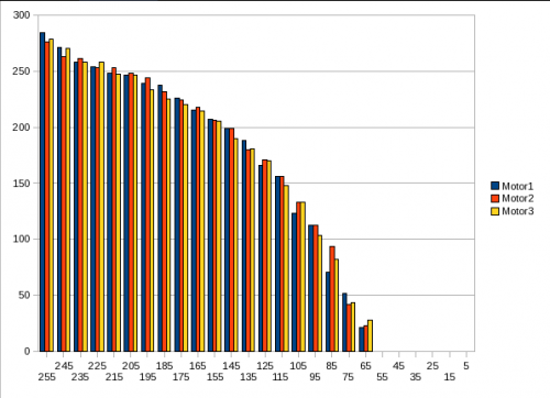
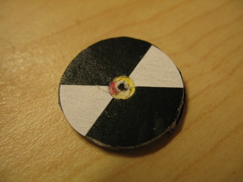
Than I added "wheel" encoders to the robot. In fact the encoders are not on the wheel, but on the "back" end of the motor shaft. This provides smoother control, because the encoder is not on the geared down shaft. I choose to make an encoder from optoreflectors, because the ready-made encoders are very expensive and has too high resolution (such as 300 CPR). The encoder discs are made from a CD. It may be crude, but I used a pair of scissors to cut small discs and drilled a hole in the middle for the shaft. Thare are two reflective and two non-reflective quaters on the discs (I used black tape to cover the non-reflective quaters). In the picture you can see some mesurements taken with the encoders (only a few simple charts can make your projects look so scientific).
The robot is controlled through the serial interface with simple commands. I also created a simple interface so I can control a robot with a joystick connected to the PC. The application displays the giro output and the PWM lengths from the robot (the joystick data are also displayed).
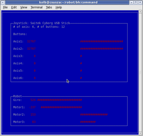
Also there is much room for improvement. The latest is a giro sensor. I plan to modify the control software to use the input from the giro to move the robot even smoother when it starts and stops. It can also help to maintain orientation during movement.
Update, 2011/09/20: New encoders
The old one looked like this.
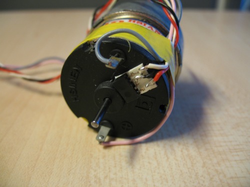
The old encoders were TCRT 1000 opto-reflectors attached to the motors with double sided tape. The sensors were attached to the microcontroller through Schmitt-trigger inverters.
It has some flaws. First it looked ugly, second it draw too much current. The new encoders look like this.
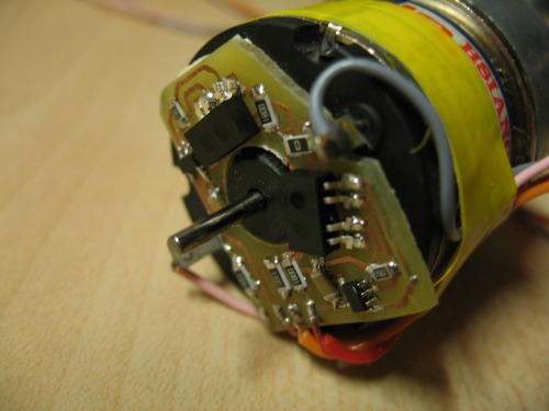
The new encoders incomporate smd parts on a small PCB board. The new encoder has two sensors so it can detect direction. I placed the sensors so I can use 4 and 8 CPR encoder discs. The new encoders did not work with the old discs, so I made new discs.
Lessons learned:
- After experimenting with the sensor positions it occured to me, that the ideal positions would be 90 degrees from each other. This way any encoder discs can be user with odd number of dark/white areas.
- The sensors are too sensitive. I mesured the length of the dark and lights cycles sensed by the encoders. The encoders sensed much smaller dark areas on the disc than white areas. So I changed the encoder discs and added an extra 15 degrees to the dark areas on each side. This way the sensors sensed more os less the same amount of time on dark and white areas.
The new encoder disc (the dark areas are much bigger than the white ones):
I printed the encoders (used a small postscript program), cut it and attached to the back side of the old discs.
The new discs work fine. I even made some higher resolution encoder discs and tested them. Now I only need to modify the control program to use the new encoders (coming soon).
Move around in a very cool way
- Actuators / output devices: 3x gearmotors
- Control method: micrcontroller, bluetooth serial remote control
- CPU: Atmel ATMega32
- Operating system: Linux
- Power source: 6x 1.2 V batteries
- Programming language: C
- Sensors / input devices: wheel encoders, giroscope
- Target environment: indoors mainly