


Edward
update: added code (older version 1.1) as attachment
update: Frontplate is mounted. Turned the IR sensors. Lost the abiity to detect cliffs :(
This is my second robot. The first one was for practicing soldering using a picaxe 08M prototype board. It had two modified servos, a led, an infra-red eye and a switch. I couldn't get the speed control right using the servos so I figured I should use PWM. The other problem I ran into was the program size. The 256 bytes on the picaxe08M is just not enough.
the board
I bought a Picaxe 28 starter kit which is great for playing around, but it lacks a few features I wanted. First of all, the picaxe chip supports I2C, but since the I2C pins are fixed as digital inputs on the board. That means no eeprom chips and no I2C display. Also, the PWM pins of the picaxe 28 are also configured like that and I really want speed control.
So I decided to put my newly acquired soldering skills to the test and build a board from scratch. I intended to put the power-stuff on the board together with the motor driver and build it as a I2C slave. When I was done I figured I had enough space left to add two 32K eeprom chips and a few headers (for the sonic rangefinder, infrared and servos)
The 32K eeproms are to store texts, movement sequences and sensor-conditions. I don't know how yet, but I allready tested some primitive menu using the serial cable to fill the eeproms from my laptop. This program uses about 500 bytes so I might be able to leave it there alongside the rest of the programming. we'll see.
Here's the result
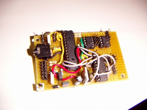
It takes 7.2V from 6 rechargable NiMH batteries. One jumper can be removed to provide a powerswitch and the second jumper can be removed to disconnect the logic circuit from the motor power, so you can use a separate 5V powersource. I added a diode just in case I put the power connector on the wrong way.
Hidden beneath the wires on the top, there is a third jumper which can be removed in case I want to use this board as a I2C slave. The jumper connects the pull-up resistors for the I2C bus.
The body
I am building the body out of expanded-PVC. It is great stuff! Very easy to handle and you cut through it like butter. The ground plate is 5mm thick with a hole sawn out. That takes 5mm of the first battery case, which is mounted under the plate. The other battery case is carried on the back, sort of like a back-pack.
The front will have a 2 x 8 character display from matrix-orbital (blue-ish letters on white background - looks very cool!) Still need to decide where to place a small button and the reset button, along with a few LEDs.
The main board will be skrewed on and hang from the top plate. Hopefully the serial jack connection will be reachable from the outside that way. On the front (bottom) two IR-rangefinders will be mounted to be used as bumper switches. I hope I can figure out some clever way to mount them at an angle. The wires on those IR thingies are really sticking out. Very hard to mount those things without the wires showing.
Tracks
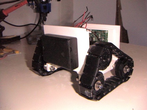
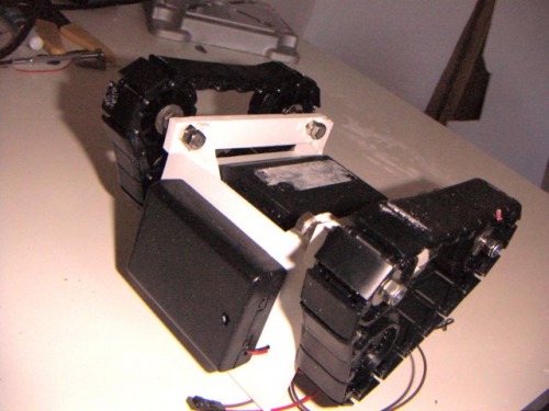
I use tracks to enable the robot to drive over stuff. (My first robot could get stuck on a magazine on the floor) Because the motors are pretty thick, I decided to mount two idlers below the ground plate so that the motor is inside the body. That should give me more ground clearance. The idea is to get a Wall-e look.
The tracks are mounted using 5mm bolts from the local hoby shop. I bought some extra rings and stuff to get the distance right. It was a lot harder than I expected to get those tracks right. Too loose and the motor just spins without moving the tracks and 2mm too tight and the left and right tracks dont run at the same speed.
First Moves
OK. The top board is on. I didn't cut the hole for the wires of the head yet, but I really wanted to see this thing moving.
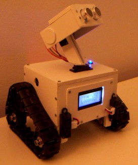
I renamed the robot to Edward (after Edward Scissorhands) because I'm afraid I don't have enough space to add any kind of arms or hands. He'll probably end up with dummies or no arms at all.
The treads are very smooth which is great for turning, but very bad when trying to drive over an obstacle on a wooden floor.
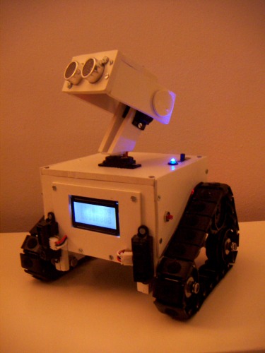
head attached
Edward has sort of half a head now. I still need to fix a frontplate to cover the sides of the display, finish the head (not a very nice job I did now) and fix the sharp IR rangefinders. That SRF05 is not very good at detecting the floor. I guess the ultrasonic pulse just bounces off the floor and doesn't get detected.
I was hoping I could get it to look down and "see" the floor or "see" cliffs or table edges. I'm going to have to use the IR rangefinders for that.
Done
I'm calling this one finished. I'll spend a few cold winter evenings trying different programs, but this design just isn't very good. Lets look at what I think I've learned.
I tried a separate power supply, but that didn't solve the resetting of the display problem. Which means I'll need to shield the internal wires or something. Maybe the problem is that I use 7.2V through a diode, making it 6.6V and then through a voltregulator. Maybe the 6.6V is too little for the regulator, but I'm afraid those cute little servos will melt down when I give them the full 7.2V. Anyway: my next bot will have 2 powersupplies.
Another problem is the motor driver. I really don't like the 1.4V voltage drop of the L293D. I'm experimenting with hooking up servo-electronics to different motors to be able to run them without the voltage drop and using 1 output pin for control. Maybe i'll drive the next bot with 9V or 12V and use a switching voltregulator to bring it down to 5V for the servos. I'll start playing around with relays. I want better speed!
Thirdly: the weight is distibuted wrong. I didn't think it would become a problem, but edward falls on his back quite easilly.
And then the sensors. I knew the optimal way to combine IR and US sensors would be to have the SRF05 on the belly and two IR sensors on the head, but I went for looks. The IR's are now mounted at an angle sideways so that they look in front of the treads. They don't look down though. So Edward cannot detect cliffs anymore The head is only usefull for detecting large vertical objects and for cute looks. I'm considering building a Frits!LDR with lenses. Something that is more stable then the IR sensors and less sensitive to surfaces that don't face the sensor directly.
This was a nice project and the result is a cute little bot with a display two 32K eeproms that I can program endlessly. On to the next....
Avoid obstacles... look cute... lots of programming to be done.
- Actuators / output devices: 2x Solarbotics GM3, 2 servos for the head
- CPU: Picaxe 28x1
- Power source: 7.2V NiMH from 6 penlites (2 x 3)
- Programming language: Picaxe basic
- Sensors / input devices: 1 SRF05 and 2 IR distance sensors