


Edge avoiding arduino robot
hello guys...this is our project..
this project is how to build edge avoiding robot using arduino and ir sensor..
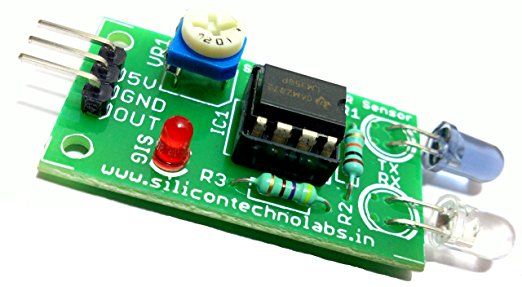
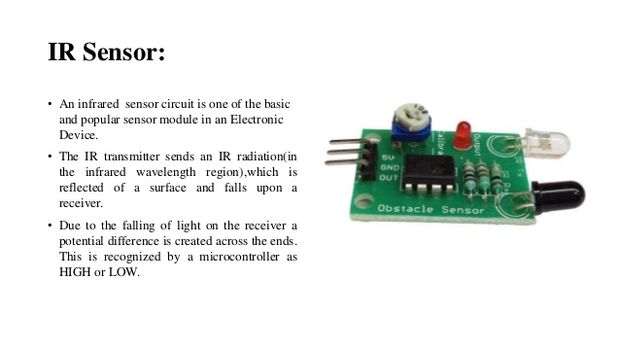
IR Sensors work by using a specific light sensor to detect a select light wavelength in the Infra-Red (IR) spectrum. By using an LED which produces light at the same wavelength as what the sensor is looking for, you can look at the intensity of the received light. When an object is close to the sensor, the light from the LED bounces off the object and into the light sensor. This results in a large jump in the intensity, which we already know can be detected using a threshold.
Step 1: Components
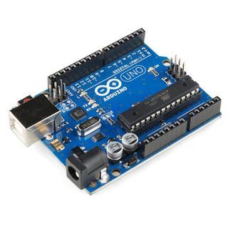
1:-arduino uno
2:-two ir sensors
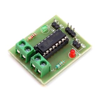
3:-l293d motor driver
4:-battery(power bank)
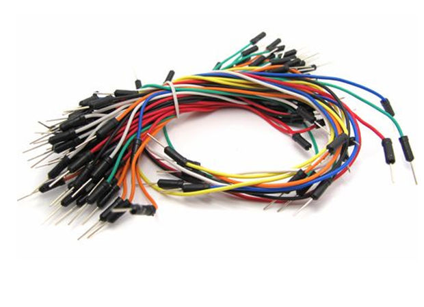
5:-jumper wires
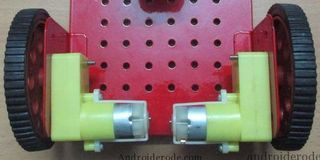
6:-two dc motors
7:-one chassis
8:-caster wheels
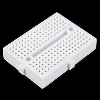
9:-mini breadboard
Step 2: Ir Sensors Connection
so
we have two ir sensors module...
left ir sensor and right ir sensor which have
vcc,gnd and op..
vcc is connect to +5v
gnd is connect to gnd
op connect to pin of arduino
Step 3: Circuit Diagram
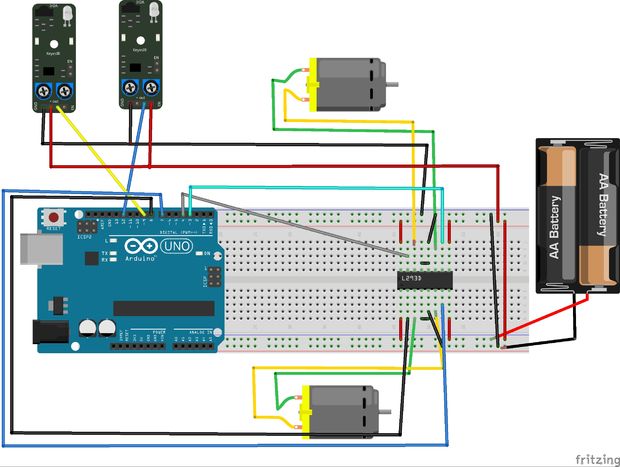
two ir sensors....
so left ir sensor op means output pin connect to the.....9pin of arduino
right ir sensor output pin connected to the....12pin of arduino
two ir sensor's vcc............connect to +5v
ang gnd ...connect to gnd
so l293d motor driver:-
8pin of arduino....connect to.....2pin of l293d
7pin of arduino....connect to.....7pin of l293d
4pin of arduino....connect to.....10pin of l293d
3pin of arduino....connect to.....15pin of l293d
vcc is connect to +5v
and gnd is connect to gnd to the 9v battery...
Step 4: If You Used As L293d Ic
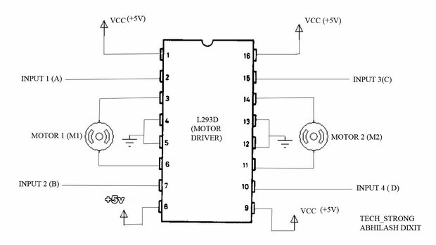
if you use l293d ic instead of l293d motor driver..
even its will be easy for connection....
l293d ic have 16pin... 1,8,9 and 16 pin connect to +5v. and 4,5,12,13 pin connect to gnd...
input 1,2,3 and 4pin is connect to arduino pin..
output is connect to left motor and right motor..
input 1 and 2 is connect for left motor..
and input 3 and 4 is connect for right motor..
Step 5: Working Procedure
Edge Avoider robot is same as line follower.
In these types of robots, we generally use behaviour of light at black and white surface.
When light fall on a white surface it will almost full reflects and in case of black surface light is absorbed by black surface. This behaviour of light is used in an line follower robot as well as edge avoider robot.
Here.........
we have used IR transmitter and receiver also called photo diodes are used for sending and receiving light. IR transmits infrared lights. When infrared rays falls on any surface except black or much dark surfaces, it’s reflected back and catched by photodiode and generates some voltage changes. When IR light falls on black surface, light is absorbed by the black surface and no rays reflect back, resultantly photo diode doesn't receive any light or rays.
Here in this Edge Avoider robot when sensor senses white surface then microcontroller gets 0 as input and when senses black line controller gets 1 as input.
Step 6: Uploading Code
after connection...
coding is needed for this project so..
#define LS 9 // left sensor
#define RS 12 // right sensor /*-------definning Outputs------*/ #define LM1 8 // left motor #define LM2 7 // left motor #define RM1 4 // right motor #define RM2 3 // right motor void setup() { pinMode(LS, INPUT); pinMode(RS, INPUT); pinMode(LM1, OUTPUT); pinMode(LM2, OUTPUT); pinMode(RM1, OUTPUT); pinMode(RM2, OUTPUT); } void loop() { if(digitalRead(LS) && digitalRead(RS)) // Move Forward { digitalWrite(LM1, HIGH); digitalWrite(LM2, LOW); digitalWrite(RM1, HIGH); digitalWrite(RM2, LOW); } if(!(digitalRead(LS)) && digitalRead(RS)) // Turn right { digitalWrite(LM1, LOW); digitalWrite(LM2, HIGH); digitalWrite(RM1, HIGH); digitalWrite(RM2, LOW); } if(digitalRead(LS) && !(digitalRead(RS))) // turn left { digitalWrite(LM1, LOW); digitalWrite(LM2, HIGH); digitalWrite(RM1, HIGH); digitalWrite(RM2, LOW); } if(!(digitalRead(LS)) && !(digitalRead(RS))) // stop { digitalWrite(LM1, LOW); digitalWrite(LM2, LOW); digitalWrite(RM1, LOW); digitalWrite(RM2, LOW); } }
copy the code and paste in arduino programme...
Step 7: Result
copy the code and paste to in your arduino.......
plz see our video on you tube of our channel s_r tronics to make this project easily ........
https://m.youtube.com/watch?v=6sH3b7yBUVs