


EDGE AVOIDER USING IR PAIR WITH ADJUSTABLE POTENTIOMETER
CIRCUIT DIAGRAM:
CONTROL CIRCUIT:
CONTROL CIRCUIT DIAGRAM:
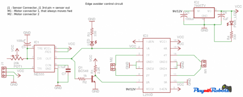
Now a question may arise that what is the use of NE555 timer in this circuit? The answer is NE555 is used as a monostable vibrator i.e. once triggered (Voltage at pin 2 falls below Vcc/3), a high logic pulse of specific time will appear on the output pin i.e. pin 3. The width of this pulse depends on the Resistance R (between 7th pin and Vcc) and capacitor C1 by the equation
T (pulse width in seconds) = 1.1RC1
Now I have connected a variable resistance of 20K in place of R so that we can adjust the pulse width. So the maximum pulse width possible from this combination is 2.2sec.
Till now, we are able to generate a pulse of fixed time whenever sensor comes out of the table. We will be using this pulse to reverse the direction of one motor in order to make a in-place rotation for certain duration. For this a transistor is used as NOT gate. Adjust the duration of this in-place rotation by changing the pulse width such that when edge is detected angle of rotation should be in-between 110-150 degree.
NOTE: When powered on, the robot will make an in-place rotation while placed on table and after that will continue normally.
Combining all:
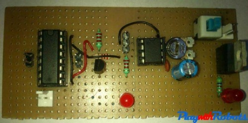
Now sensor, motor driver circuit, and chassis are ready so lets combine them all!.
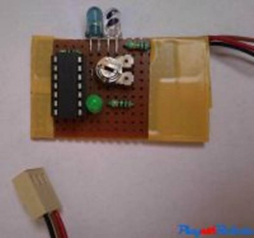
Sensor placement is important, fix it in the front of the robot by extending robot chassis. During robot's motion sensor may vibrate, adjust the threshold and height of sensor such that its output will not fluctuate. The picture below will give you an idea.
Robot will be move forward as long as the sensor detects an surface under it. As soon as edge detector sensor goes out of the table, the robot will make an in-place rotation greater than 90 degree and then continue as per sensor value
- Actuators / output devices: Acrylic sheet, General Purpose Board and two DC motors
- Control method: L293D, NE555 IC, one sensor made using IR LED, photodiode and LM324 IC
- CPU: none
- Power source: one 9V battery for MCU and IR
- Programming language: none
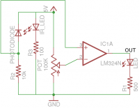
- Sensors / input devices: IR SENSOR PAIR WITH ADJUSTABLE POT
- Target environment: indoor