


Doorbell for unwanted guests
A doorbell for unwanted guests (aka Useless Machine) with PIC12F1840, a mechanical finger moved by a geared DC motor, a L293D driver, a limit switch and a speaker.
Dear LMR,
I am a 10-year-old girl and this is my first robot with MCU after I learnt basics of programming in C (I made a few simple 555-based robots before). It is also my first wooden box made myself so please kindly excuse how it looks J.
The main parts
- MCU: PIC12F1840
- Inputs:
o Activating switch: a wall-type rocker
o Limit switch: a lever-type salvaged from a printer
- Outputs:
o Bidirectional motor driver: L293D
o Geared DC motor salvaged from a scanner
o 0.5W speaker switched by PWM via IRLB8743 N-MOSFET
o Blue LED
- Power: 9 VDC (6x AA battery) for a motor and speaker, 5 VDC via MCP1702 linear stabilizer for MCU and the rest.
- PCB: universal line PCB (e=0.1´´)
Function:
When an activating switch SW2 is pressed, LED lights on, the speaker barks and the motor starts moving the mechanical finger to turn off the switch again. Then the finger moves back until it hits a limit switch SW1 that stops its movement or the activating switch SW2 is pressed again.
Functional scheme:
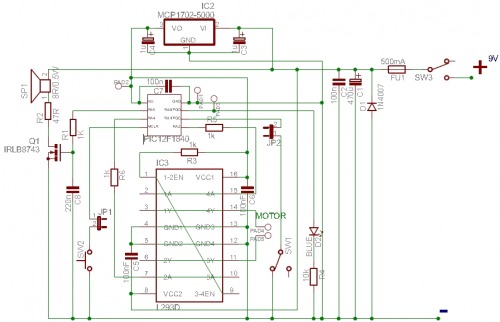
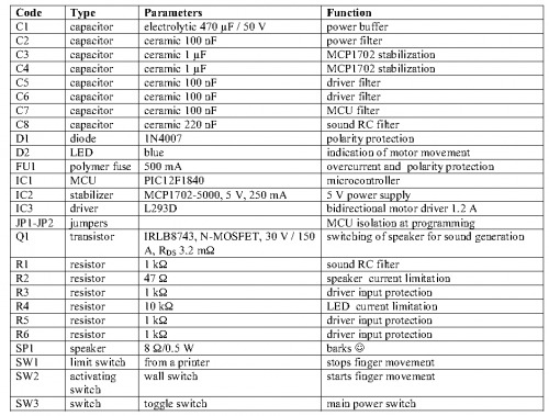
Table of components
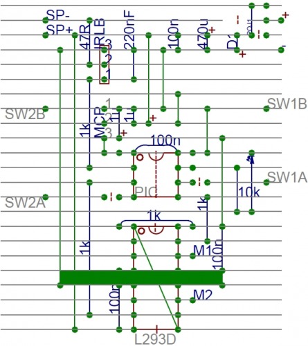
Soldering scheme (universal line PCB; e=0.1´´):
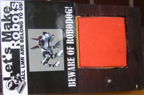
Top of the box:
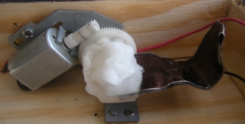
Motor with a mechanical finger (held by polymorph):
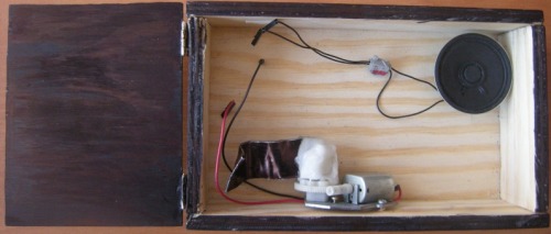
Empty box with a motor and a speaker:
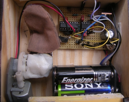
Motor with electronics and battery:
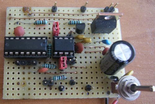
PCB top:
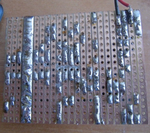
PCB bottom:
Now I plan to hack an old RC car to convert it to an autonomous line follower for a few competitions in robotics of youth this spring. I hope that it will be little less useless machine than this one J.