Download the Arduino IDE software directly from the Arduino website:
https://www.arduino.cc/en/Main/Software
Open the DIY_ROBOTICSEDUCATIVECELL_Arduino_V1_0.ino file included in the DIY_ROBOTICS_EDUCATIVECELL_V1_0.zip compressed folder.
Connect the Arduino Micro to your computer with the USB cable.
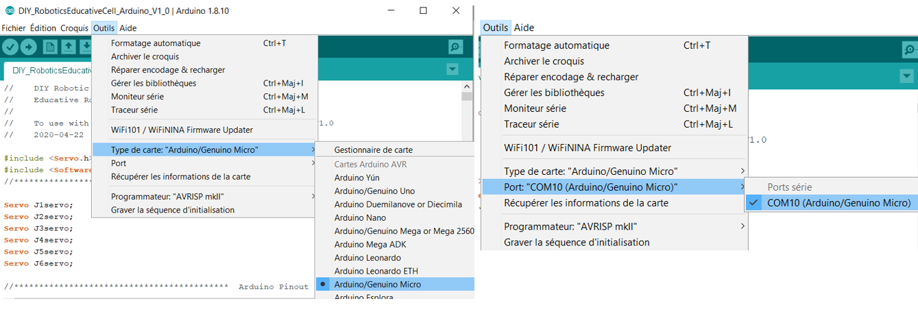
Select the type Arduino / Genuino Micro and the correct communication port.
Refer to next image.
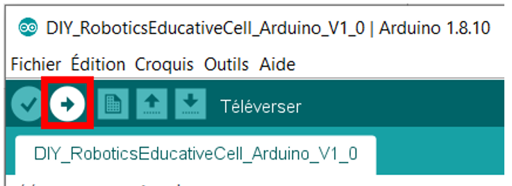
Program the Arduino Micro by pressing the Upload button:
Refer to next image.
1. Overview
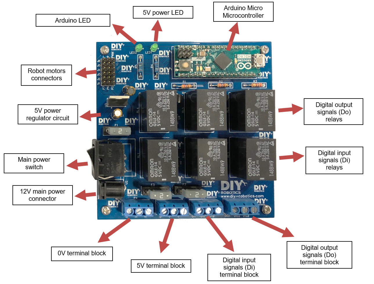
The electronic controller of the robotic educative cell is the bridge between the programming software and the robot. The microcontroller used on the printed circuit, the Arduino Micro, performs the following tasks:
- • Communication between the electronic controller and the programming software
- • Control of the 6 robot motors (5V servo motors)
- • Control of 3 digital output signals (0-5V logic levels)
- • Reading of 3 digital input signals (0-5V logic levels)
Refer to next image to see the description of the PCB.
2. Printed circuit board (PCB) order
The printed circuit board (PCB) of the robot controller can be ordered from any PCB manufacturer with the "GERBER" files included in the compressed folder DIY_ROBOTICS_EDUCATIVECELL_V1_0.zip.
We suggest you to order from the manufacturer JLCPCB (jlcpcb.com) which offers a fast, simple service at a very low price. Follow the following steps to order the PCB:
- A) On the jlcpcb.com home page, select QUOTE NOW, then Add your gerber file.
Select the Gerber.zip file in the DIY_ROBOTICS_EDUCATIVECELL_V1_0.zip compressed folder. - B) Select the default parameters.
- C) Select Save to cart and proceed with payment to complete the order.
3. Printed circuit board (PCB) assembly
Once the robot controller PCB in hands, proceed to its assembly. You will have to solder all the components.
Each component of the PCB is identified.
bill-of-materials.pdf material list included in the DIY_ROBOTICS_EDUCATIVECELL_V1_0.zip compressed folder will help you to sort the components.
Refer to next image.
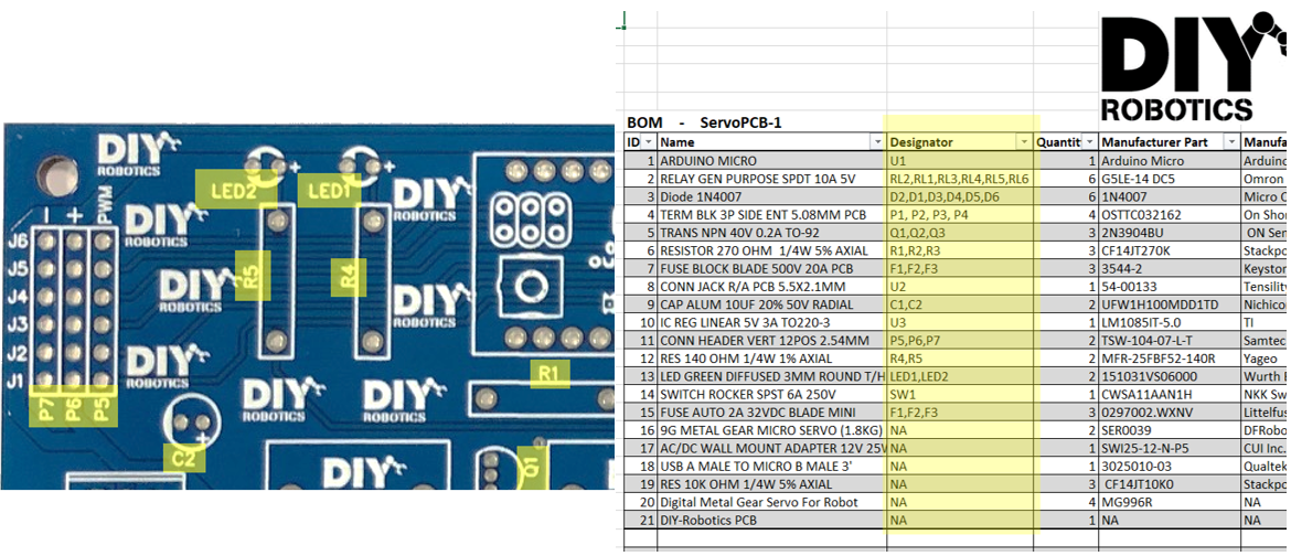
Pay particular attention to the polarity of the following components:
LED1, LED2, U1, U3, C1, C2, D1, D2, D3, D4, D5, D6, Q1, Q2, Q3
These components must be soldered the right way, otherwise they will burn. For example, notice that the light emitting diodes (LEDs) and the capacitors (C) have a long pin and a short pin. The long pin, the anode, must be inserted and soldered into the hole identified by a +.
Refer to next image to solder these components the right way.

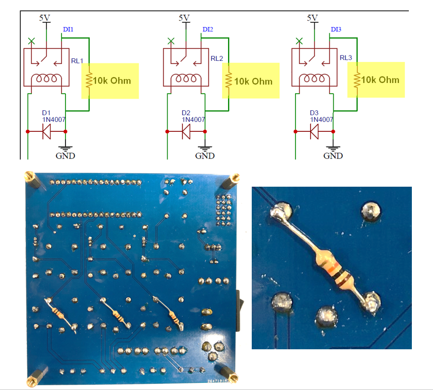
Finally, 3 resistors of 10k Ohm must be added to the circuit in order to make the digital input signals (Di) functional. These resistors are described as follow in the material list:
RES 10K OHM 1/4W 5% AXIAL
Refer to next image to see where to solder those additional resistors.
1. Overview
In order to mechanically assemble your robot, you will need the following components and tools:
- 4 MG966R servo motors
- 2 9g Micro servo motors
- 8 3D printed robot parts
- 24 metric M2 nuts
- 24 metric M2 bolts
- 2 metric M2.5 bolts
- 4 metric M3 bolts
- 3D printer
- Soldering iron
- Lighter
- Hex keys
Refer to the DIY_ROBOTICSEDUCATIVECELLV1_0_BOM.pdf material list included in the DIY_ROBOTICS_EDUCATIVECELL_V1_0.zip.
2. 3D printing
You will find the 3D files of the 8 robot parts in the DIY_ROBOTICS_EDUCATIVECELL_V1_0.zip compressed folder.
Print the parts using a 3D printer. We recommend that you use the following settings:
Top layer 4 layers
Bottom layer 4 layers
Wall 4 layers
3. Align the servos
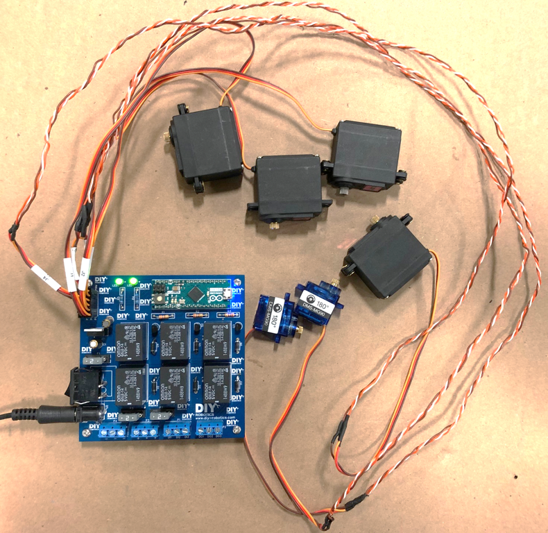
Before assembling the robot, it is important to make sure that all the servo motors are at midpoint. In order to align the servos, make sure you have previously programmed the Arduino microcontroller and assembled the robot controller. Follow the instructions below to align the servo motors:
Connect the 6 servo motors to the robot controller.
Make sure the connectors are plugged in the correct way.
- Brown wire : 0V (-)
- Red wire : 5V (+)
- Orange wire : PWM
Connect the 12V regulator to your 120V AC wall outlet.
Connect the 12V regulator to the power connector of the robot controller.
Activate the power switch SW1.
The LED1 light should turn on and the LED2 light should flash.
The robot should position all of its servo motors at 90 degrees.
You can turn off the power on the robot controller and disconnect the servo motors.
Refer to next image.
4. Insert the nuts
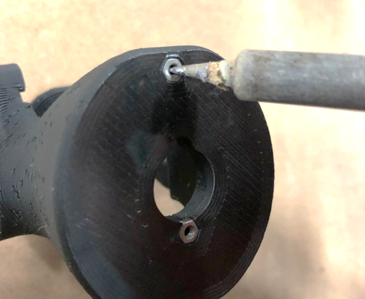
Before assembling, insert a M2 x 0.4mm nut into each hexagonal hole of the 3D printed parts to allow assembly.
Use a soldering iron to facilitate insertion.
Refer to next image.
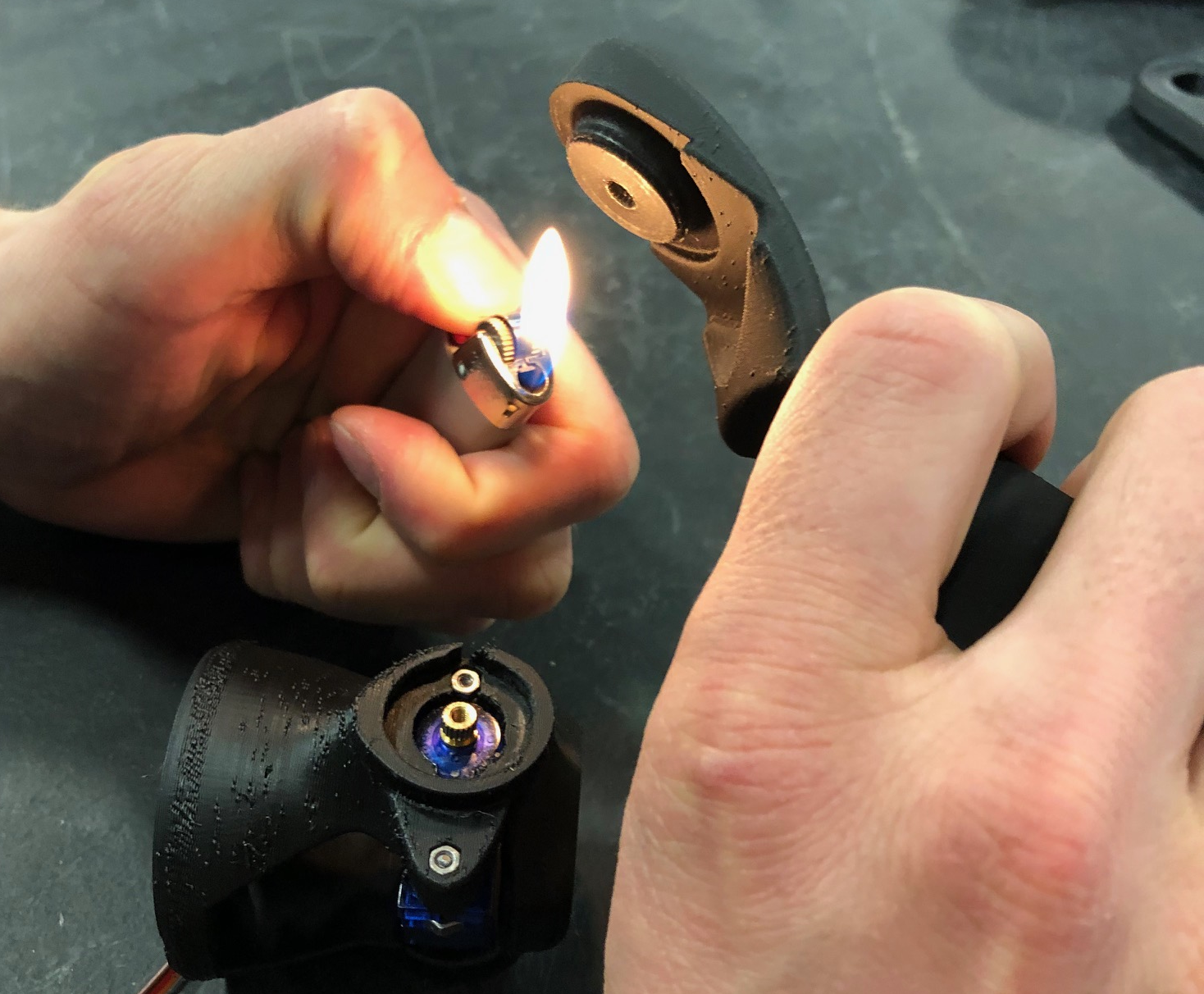
5. Cast the gears in the junction holes
The mechanical junction between the servo motors and the 3D printed robot parts are direct: the gear must be inserted directly into the hole.
To ensure a good mechanical junction, the holes are slightly smaller than the gears after 3D printing.
With a lighter, slightly heat the hole, then insert the gear of a servo motor (as straight as possible). The melted plastic will take the form of a gear. Complete the insertion by gently tightening a bolt. Repeat this step for each junction.
Be careful, overheating 3D printed parts could deform them and make them unusable.
Refer to next image.
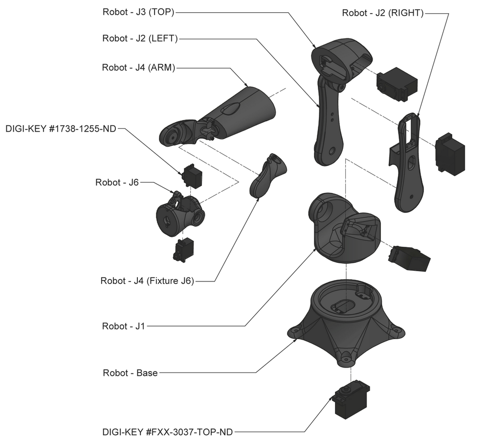
6. Assembly
Use M3 metric bolts to attach the servo motor gears to the 3D printed robot parts.
Use M2 metric bolts to attach the servo motor housings to the 3D printed robot parts.
Use M2 metric bolts to assemble the two 3D printed robot parts from J2 to J4.
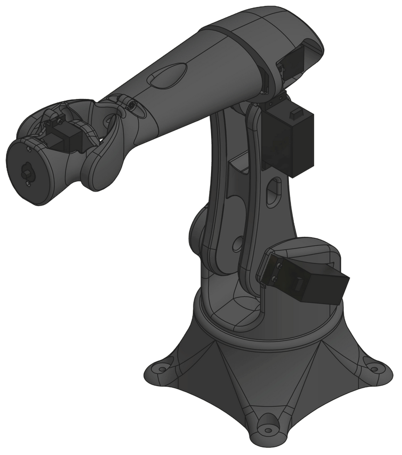
Assemble the robot so that each joint is at its mid-point (straight robot, as illustrated below).
Refer to next images.
1. Software setup
Open the setup file included in the DIY_ROBOTICS_EDUCATIVECELL_V1_0.zip compressed folder.
Follow the installer instructions to complete the installation.
When the installation is complete, run the software by clicking on the DIY Robotics icon on your desktop.
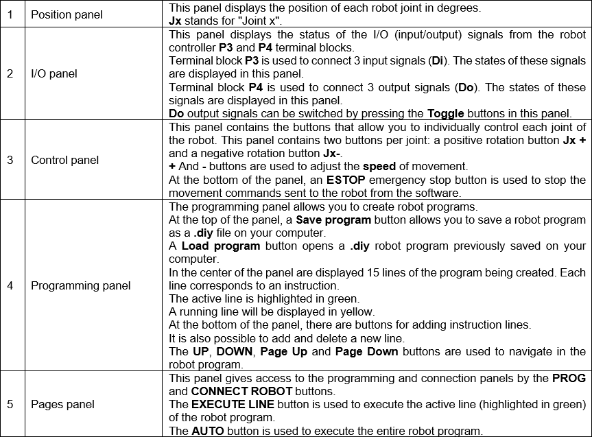
2. Navigating the interface
Refer to next images for software panel descriptions.

3. Creation of a robot program
The programming panel allows you to create a robot program with up to 200 instruction lines. Here is a description of each type of instruction:
POINT instruction
Saves a robot point (position).
Executing this instruction will move the robot according to the saved position and speed.
To save a robot point in an instruction, manually move the robot at the desired position and select the desired movement speed using the buttons in the control panel. Press the Point button. An instruction line is then added in the programming panel. The instruction line shows the value in degrees of each joint as well as the speed of movement.
DO instruction
Changes the state of a Do output signal.
Executing this instruction will change the state of one of the output signals Do (ON/OFF).
To create a DO instruction, press the Do button. A parameter panel is displayed. Choose the Do output signal number (1, 2 or 3) as well as the desired state (ON or OFF). Press the Add Instruction button to add the instruction.
An instruction line is then added in the programming panel. The instruction line shows the Do signal number and the change of state.
LABEL instruction
Adds a label in the robot program.
Executing this instruction will have no effect. This line is a label that will allow the JUMP instruction to jump to this LABEL instruction line.
To create a LABEL instruction, press the Jump Label button. A parameter panel is displayed. Choose the Label option and the number of the desired label (1 to 5). Press the Add Instruction button to add the instruction.
An instruction line is then added in the programming panel. The instruction line shows the label number.
JUMP instruction
Jumps to the program line that contains the corresponding label.
Executing this instruction will cause a jump in the program to the line that contains the corresponding label.
To create a JUMP instruction, press the Jump Label button. A parameter panel is displayed. Choose the Jump option and the number of the desired label (1 to 5). Press the Add Instruction button to add the instruction.
An instruction line is then added in the programming panel. The instruction line indicates the number of the target label.
If several labels have the same number, the JUMP instruction will jump to the first corresponding label from the top of the program.
If there is no label corresponding to the JUMP instruction number, the program will jump to the last line of the program.
WAITDI instruction
Waits for a specific state of a Di input signal.
Executing this instruction will put the robot controller on hold as long as the state of the Di input signal is different from the expected state.
To create a WAITDI instruction, press the Wait Di button. A parameter panel is displayed. Choose the Di input signal number (1, 2 or 3) as well as the desired state (ON or OFF). Press the Add Instruction button to add the instruction.
An instruction line is then added in the programming panel. The instruction line indicates the Di input signal number and the expected state.
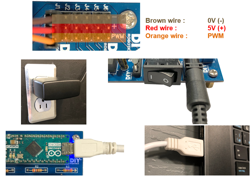
1. Electrical connections
Connect the 6 servo motors of the robot to the robot controller.
Make sure the connectors are plugged in the correct way.
- Brown wire : 0V (-)
- Red wire : 5V (+)
- Orange wire : PWM
Connect the 12V regulator to your 120V AC wall outlet.
Connect the 12V regulator to the power connector of the robot controller.
Activate the power switch SW1.
The LED1 light should turn on and the LED2 light should flash.
The robot should position all of its servo motors at 90 degrees.
Connect the USB cable from the robot controller to your computer.
Refer to next image.
2. Run the software
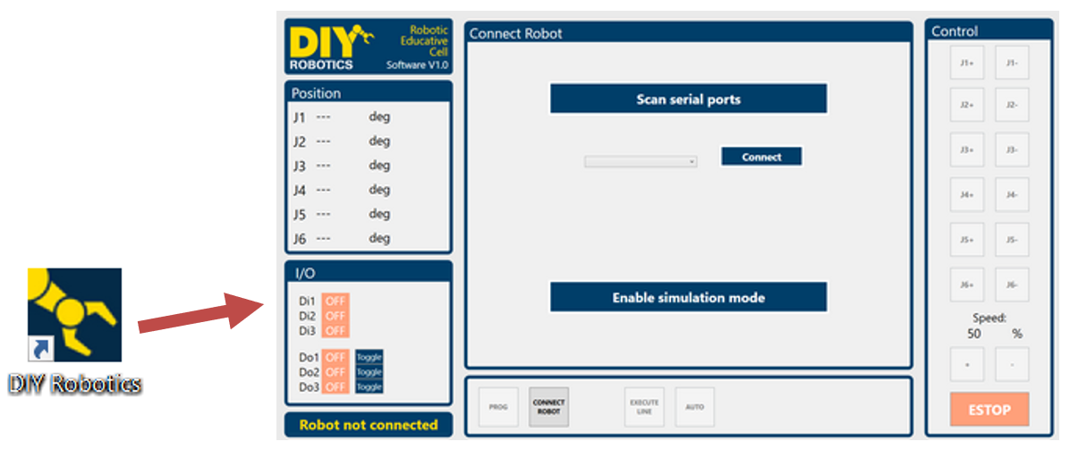
Run the DIY Robotics Educative Cell V1.0 software by clicking on the DIY Robotics icon on your desktop. The software opens on the connection panel.
Refer to next image.
3. Set PC <-> Robot serial communication
Press the Scan serial ports button.
Select the correct communication port from the drop-down list.
Press the Connect button.
Refer to next image.

4. Let the creation begin
Control the robot from the control panel.
Create your robot program from the programming panel.
Have fun!

Want to go further?
You enjoyed learning about the world of industrial robotics? You’re ready to pimp your new robotic arm? Join the DIY-Robotics Forum now! The DIY-Robotics Forum is a place to talk programming, share ideas and solutions, and work together to build cool stuff in a supportive, smart community.
Need help?
The DIY-Robotics community is there to help if you need some support as you build the DIY-Robotics educative cell. Subscribe to the DIY-Robotics Forum and ask your question to the community.
https://diy-robotics.com/


