


Dimensional Ultralancer: Vulcan Five - Sumobot
Hello All,
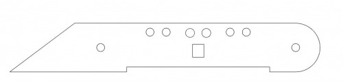
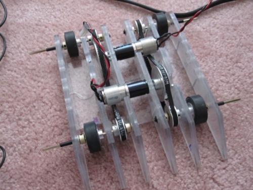
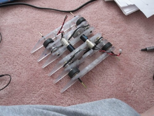
This is my first, hopefully of many, robots I am posting at this site. I am part of the University of Saskatchwan IEEE Robotics club and have been building robots for several years now. This is my attempt at making a low profile sumo to sneakily sneak past other robots. I got the inspiration for the robot from watching the very low RC controlled combat bots, and I though I could do that. So i got to work with some doodles on a piece of paper. What I came up with was this:
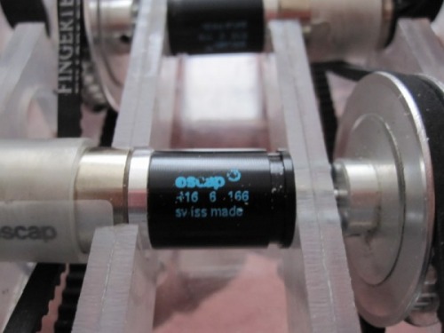
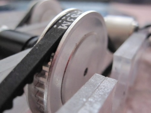
I then set to work cadding the robot up so I could get the dimensions right. I use the free program from emachineshop cause it exports to DXF and its free. I also use CadSTD lite since emachineshop doesn't have a layer option. The next part was to decide on a drive system. At the recent sumo exhibition I noticed that most of the robots were using 4WD, which gave them added traction and power. I liked the idea of 4WD but didn't want to have the added weight of two more motors. So I sat and thought for a while about what to do about the situation. As I was rummaging about my stuff for ideas I found 2 of these guys:
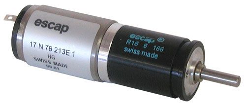
I bought them a long time ago in an attempt to make a linefollower robot. But to my dismay it had a really slow shaft speed, much slower than I would have liked. So they sat in the motor bin collecting dust. As soon as I saw them the gears in my head started to turn. Even though they were slow they had a lot of power. If I could just up the speed some more they would be perfect. I then thought: "How about using a belt and pulley system?". This would take care of the speed issue and possible be less weight then two more motors.
My good friend at Fingertech Robotics sells a large selection of belts and pulleys so I was in luck. I set back to work cadding the dimensions and positions of the pulleys and motors. My first attempt at the output ratio was 2:1 using two 15 teeth pulleys and a 30 tooth pulley. emachineshop told me I would need a belt with the circumference of approximately 290 mm (almost 12 inches). With that in place I set about making the other parts of the body with no regard for weight (I figure that I could just drill some holes in places to get it underweight).
Next came the wheels. I wanted wheels that had deatch grip (or close to it) traction. I've been using foam rubber tire, which are nice and light and also have good traction. But rubber offers better traction. Again while rummaging around in my stuff I found 4 of these (you will see a trend here pretty soon):
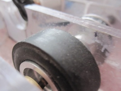
Solarbotics 31mm diameter (almost 1-1/4 inches) rubber wheels. They were perfect. Aluminum hubs to make them lightweight complete with set screw. Don't remember why I bought these though. I then set about the actual construction of the body. I have a Sherline CNC mill which is great for cutting out shapes. After I was done with the cad and satisfied with the look I set up the Gcode with SheetCAM and let the mill do its thing. The body is made with 1/8 inch thick Lexan sheets which are then cemented together to make the final thickness of 1/4 inch for the body parts.
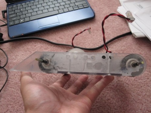
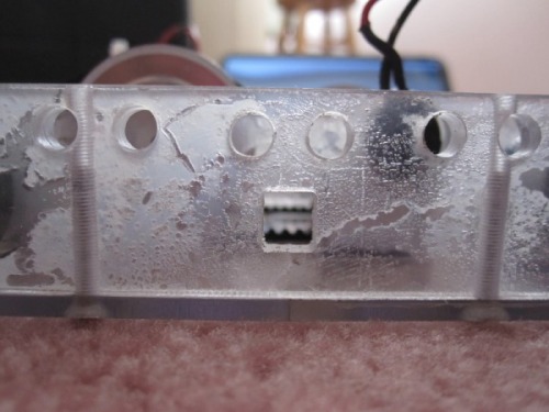
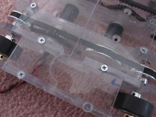
With the parts machined it was time to put it all together. The parts are cemented together with Tamiya extra thin cement (really smelly stuff). And fastened to the base with some sort of metric screw. I thought they were 4-40s but they didn't fit in the tap threads, I managed to find the correct tap somehow (I'll put what it is later). On a side note, if you notice in the picture below that the base has a strange section in the middle:
I had to do this so I could cut the base on the mill. I wasn't quite sure if I could cut the whole thing out so I split it into two parts with some mating connections.
ATTEMPT 1
I got the 30 and 15 teeth pulleys and belts from Fingertech. I had to go with a bigger belt then expected cause they didn't carry anything around 290mm. What I got was 321mm. At this point I figured that I could just tension it somewhere and it would all be good........ Dun dun dun not really.
There was no place I could tension it enough. So I had to think of something.
ATTEMPT 2
Fortunately for me I live in the same city as Fingertech. So I packed up my robot and drove there. I told them my problem and they helped me out . We came the conclusion that I would have to get bigger pulleys to make up for the slack. The guys there were nice enough to let me try out the selection they had until I had something that would work. I settled on 2 38 teeth and 4 22 teeth. Doing the math it would give me about 1.77:1 ration, which was still pretty good. I still had some slack but the good part was the motor itself was actually tensioning the belt. I exchanged the old pulleys with no issue and was on my way home.
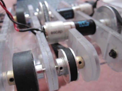
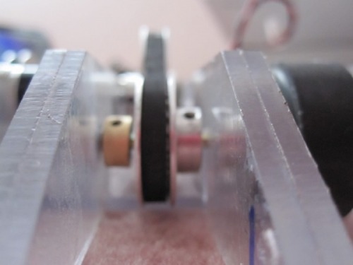
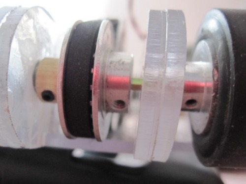
With the pulleys and belts in place I did a test run with just a battery. I noticed that the belt was slipping sometimes which meant I needed more tension. Looking at the whole setup I would need about 2-3mm of thickness added somehow to the motor. As always, while looking through my stuff I found a 1 inch diameter acrylic rod. Great! I threw that sucker on the lathe and turned it to the correct diameter and bore a hole that would fit the motor. here is the result:
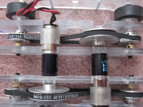
Perfect tension and no slipping.
And now for the brains of the operation. In keeping with my finding stuff theme. I found a Baby Orangatan which was a prize from a while back that I got from Pololu . This version has been obsoleted, but not to worry cause they just have a better version with a beefier chip.
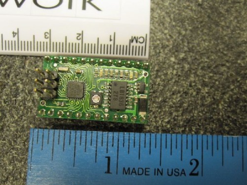
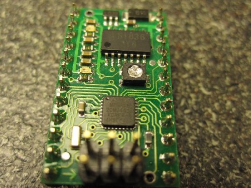
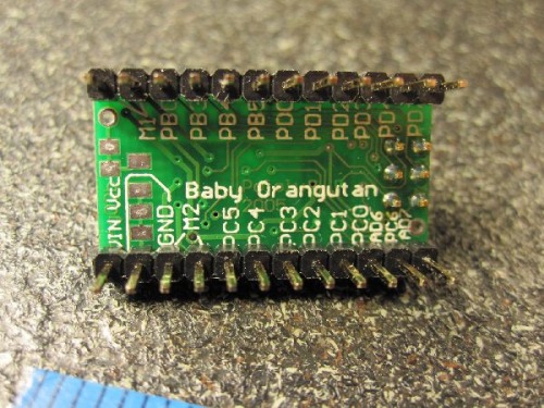
This little module contains an Atmega48 with a 20MHz oscillator, 5V voltage reglator and motor driver. Being a Microchip PIC fan, I don't have that much experience with Atmel products, so now is a good time to learn. This little guy also saves me weight and space.
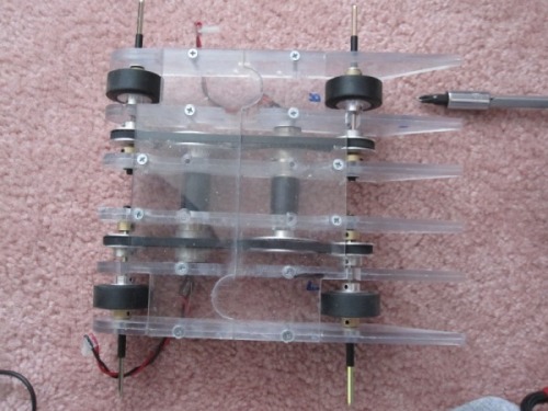
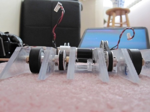
Here are some pictures for your viewing pleasure until I finish my robot. I will keep updating until it is done.
As a final note the name comes from here. Under the mecha name generator. I recommend you use it cause having an awesome robot isn't enough. It has to sound awesome too.
- Actuators / output devices: Portescap (escap) Gearhead R16 6 166, Portescap (escap) Motor 17 N 78 213E 1
- Control method: autonomous
- CPU: Pololu Baby Orangatan (Atmega48)
- Power source: 11.1V 360mAh lipoly
- Programming language: C
- Sensors / input devices: pna4602m, QRD1114