


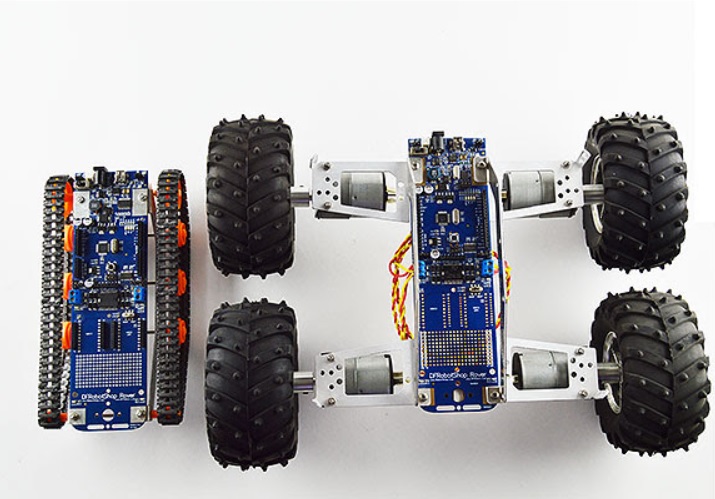
The DFRobotShop Rover 4WD experiment was intended to be the answer to many customer requests for a 4WD version of the DFRobotShop Rover. The PCB (which was an integral part of the lightweight frame) was always meant for tracks, and the additional omni/meccanum brackets were meant to be used with specific motors / wheels. The question then became - could this be adapted for use as a four wheel drive robot?
https://www.robotshop.com/en/dfrobotshop-rover-robot-controller-board-v2.html
https://www.robotshop.com/en/lynxmotion-mmt-02-motor-mounts.html
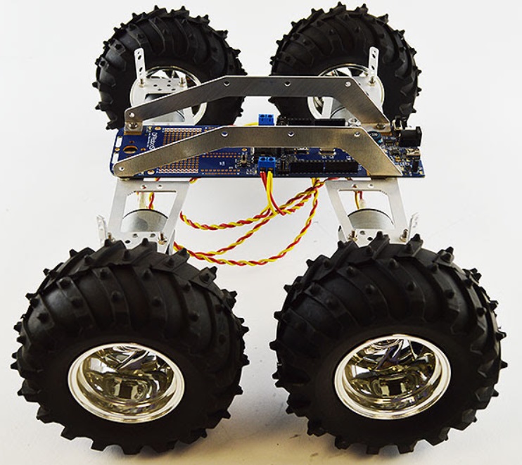
Since the PCB on its own doesn't provide much rigidity, it was important to reuse the brackets in the same way they were used for the Meccanum and omniwheel variations, that is flipped on to the top of the PCB. Given the dimensions of the existing frame, the wheels would end up quite far apart. This creates an issue since with 4WD “skid steering” designs, the wheels both roll and slip sideways. The farther apart they are, the more sideways force is needed when doing a small radius turn. The larger the radius of the turn, the easier it is for the robot. The farther apart the wheels (i.e. width) , the easier it would be for a robot to turn on the spot. If the front and back wheels are placed far apart, the force needed to move sideways becomes significantly higher.
The motors would need to be proportional in size to the dimensions and weight of the robot, while at the same time being powerful enough to be used as a 4WD system. DC gear motors seemed like the most suitable actuator, so it was a matter of finding a suitable one based on rpm, torque and nominal voltage. Ideally a 6mm diameter output shaft would make it compatible with the most hubs / wheels in the hobby robot market.
RobotShop had offered the Dagu All Terrain Wheel Set which retailed for $28 USD and included four large (120mm diameter) foam-filled wheels and four 6mm hubs. This seemed to be great value and the foam could replace a basic suspension system.
The Cytron 380rpm, 90oz-in spur gear motor seemed to offer more than enough torque, respectable rpm, low current consumption and a 6mm diameter shaft. Four identical spur gear motors were connected to each of these mounts, and connected to the board using motor wire
https://www.robotshop.com/en/gearhead-motor-wire-mw-01.html
http://www.robotshop.com/en/cytron-12v-380rpm-9027oz-in-high-power-spur-gearmotor.html
One downside was the 12V nominal input voltage, but finding a DC motor rated for 3.5 to 4.5V nominal while being of reasonable power for a 4WD system proved not easy to find. The DFRobotShop Rover PCB could still be powered at 12V without issue, but the onboard 3.7V LiPo charger could not be used, and a heavier 11.1V LiPo battery would be needed.
The first (and most evident) issue proved to be the weight of all four motors, motor mounts, hubs, wheels and 11.1V battery pack. The DFRobotShop Rover was meant to be ultralight, and upon installing the 4WD system, the aluminum brackets flexed under the load. The PCB would not be able to handle the load at all. This on its own was reason enough not to proceed.
The second issue was zero radius turning. Although the robot had no issue moving forward, backward or moving in arcs, turning on the spot proved difficult. When turning, the friction between the rubber and the floor, especially the “pegs” which protrude from the wheels (great for getting grip outdoors), caused even more flexing in the frame until the sideways force was sufficient to move the affected pegs, only to stop again.
Rather than just one aspect of the design which could be changed to resolve the problem, the following were all contributing factors:
- Re-purposing the existing brackets, which were never meant for the load nor the direction of the force was far from ideal.
- The high friction of the wheels for a “brute force” skid steer system was not ideal for indoor / flat floor.
- The motors, hubs, 11.1V battery and brackets used were far too heavy to be added to the DFRobotShop Rover frame
- A lot of power is lost (to heat) by forcing the wheels sideways in a zero radius turn.
This is not to say that the chosen parts would not be good for outdoor use, or that a more sturdy frame would not solve many of the issues. The motors were certainly powerful enough, and the locations of the wheels (width and length apart, as well as diameter) were good. In fact, simply screwing the mounting plate into solid wood and laying the DFRobotShop Rover PCB on top would likely resolve the issues, but that was not the goal of the project.
- When creating a 4WD robot, ensure the frame is strong enough for the sideways load
- Choose wheels which are appropriate to the environment, not necessarily those which look the best. Wheels made for outdoor use are really not appropriate for indoor use, and vice-versa.
- Re-purposed parts might be inexpensive, but also have the potential to cause more issues than they resolve.
This was more of a fun project based on customers asking about a 4WD version of the DFRobotShop Rover, so it was never really intended to become a commercial product.